- Home
- Product Categories
- Monochrome
- Basic 16x2 Character LCD - RGB Backlight 5V

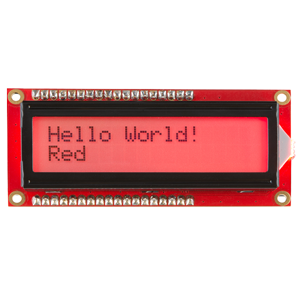
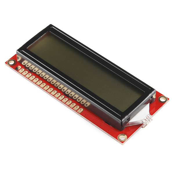
Basic 16x2 Character LCD - RGB Backlight 5V
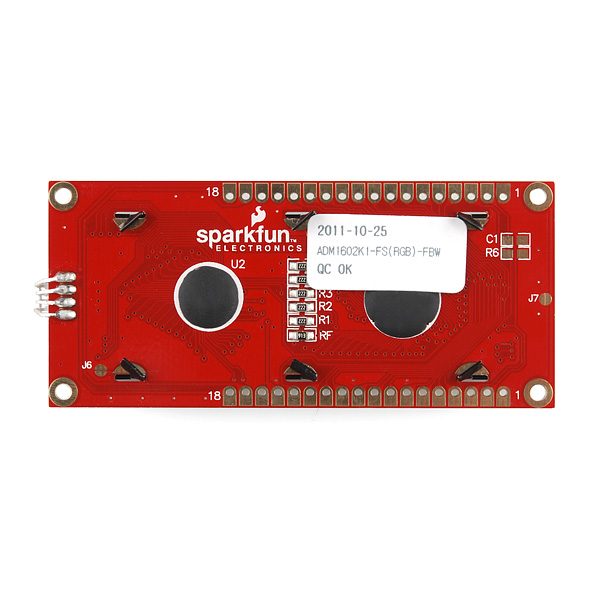
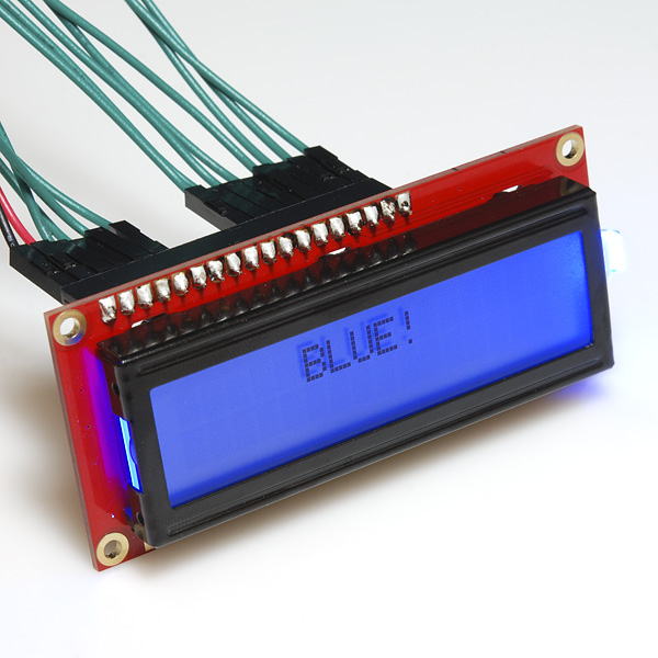
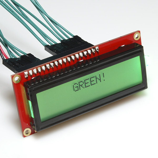
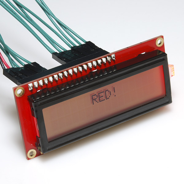
This is similar to other 16x2 character LCDs that you've seen before but with one vibrant difference: The backlight is actually an RGB LED. This means that you can change the backlight of this display to any color you want by controlling the three backlight levels. It also utilizes an extremely common parallel interface so code is freely available (check below for an Arduino example). You will need ~11 general I/O pins to interface to this LCD screen, plus an extra 3 pins for the RGB backlight.
Note: It is recommended to use a current limiting resistor with the backlight colors. You can burn out your LEDs if you do not use a current limiting resistor. Try using a 1k Ohm resistor. The backlight is controlled by pins 18, 17, and 16.
Basic 16x2 Character LCD - RGB Backlight 5V Product Help and Resources
PIC-Based Serial Enabled Character LCD Hookup Guide
May 29, 2018
The PIC-based serial enabled character LCD backpack is a simple and cost effective solution for interfacing to character Liquid Crystal Displays (LCDs) based on the HD44780 controller. The backpack simplifies the number of wires needed and allows your project to display all kinds of text and numbers.
Basic Character LCD Hookup Guide
May 28, 2019
Liquid crystal displays (LCDs) are a great way to output a string of words or sensor data to a display for visual feedback. In this tutorial, we'll learn about LCDs, how to print a string of words to a 16x2 basic character LCD and create custom characters.
Core Skill: Soldering
This skill defines how difficult the soldering is on a particular product. It might be a couple simple solder joints, or require special reflow tools.
Skill Level: Noob - Some basic soldering is required, but it is limited to a just a few pins, basic through-hole soldering, and couple (if any) polarized components. A basic soldering iron is all you should need.
See all skill levels
Core Skill: Programming
If a board needs code or communicates somehow, you're going to need to know how to program or interface with it. The programming skill is all about communication and code.
Skill Level: Rookie - You will need a better fundamental understand of what code is, and how it works. You will be using beginner-level software and development tools like Arduino. You will be dealing directly with code, but numerous examples and libraries are available. Sensors or shields will communicate with serial or TTL.
See all skill levels
Core Skill: Electrical Prototyping
If it requires power, you need to know how much, what all the pins do, and how to hook it up. You may need to reference datasheets, schematics, and know the ins and outs of electronics.
Skill Level: Competent - You will be required to reference a datasheet or schematic to know how to use a component. Your knowledge of a datasheet will only require basic features like power requirements, pinouts, or communications type. Also, you may need a power supply that?s greater than 12V or more than 1A worth of current.
See all skill levels
Comments
Looking for answers to technical questions?
We welcome your comments and suggestions below. However, if you are looking for solutions to technical questions please see our Technical Assistance page.
Customer Reviews
4.3 out of 5
Based on 3 ratings:
1 of 1 found this helpful:
works; need current ratings on backlight
Everything works fine, but the red backlight on my device is quite a bit dimmer than the green and the blue for the same current. Also, I had to switch to a 330 ohm resistor to get the red to be possibly reasonable; it draws 8.4ma R, 6.3ma G, 6.14ma B. It would be nice to know the limits of the various current draws instead of merely "Try using a 1k Ohm resistor." The data sheet does not appear to specify.
Works perfectly
I am using the LCD to display oven temperature on a custom bbq setup. Setup went smoothly and the readout works exactly as needed.
Ditto to what Labreuer said...
The display works great!
It would be nice to have more info in the spec sheet (ie. current ratings for the LEDs, the fact that "K" is common ground, better suggestion for resistor)
Another thing on the resistor, I don't know if this product is similar to Adafruit's display... they say you don't need the resistors: https://learn.adafruit.com/character-lcds/rgb-backlit-lcds
It would also be nice if it came with a header, at least loose in the package.
Quick question for you guys this morning, I have 4 of those screen hooked up in parallel with a different enable for each screen. I can print whatever character I want on any display. The problem that I have is that a weird characters are showing up after a couple of minutes to a couple of hour. It doesn't erase what was initially written, but it is kind of annoying.
Any clue about what is going on?
-------------------- Tech Support Tips/Troubleshooting/Common Issues --------------------
Example Code
There was a customer [ https://www.sparkfun.com/products/10862#comment-505c54de757b7f2a26000000 ] that wrote example code for this product. Try looking at his GitHub repository [ https://github.com/lImbus/ArduinoShield_SFE_2x16LCD_RGB/blob/master/ArduinoShield_SFE_2x16LCD_RGB/ArduinoShield_SFE_2x16LCD_RGB.ino ] .
Current Limiting Resistor
It is recommended to use a current limiting resistor with the backlight colors. You can burn out your LEDs if you do not use a current limiting resistor. Try using a 1kOHm resistor.
LCD Backpack
To reduce the number of connections, maybe you can use the serial enabled backpack [ https://www.sparkfun.com/products/258 ] to control the characters being sent to the LCD. One thing to note is that the RGB 16×2 LCD has a different pin out on pins 15 and 16. Also, the RGB 16×2 LCD has two additional pins to control the backlight colors. The LCD backpack would not be pin to pin compatible like the other basic character LCDs but you would be able to send serial characters.
I'm so mad. I burnt out the red and green LEDs because no where on the data sheet does it say anything about using a resistor. Make sure you use 1k resistors on pins 16,17,18!!!
For them as me, that do not find schema to activate RGB backlight : Pin 15 to the GROUND + Pin 16 to +5V = RED backlight + Pin 17 to +5v = GREEN Backlight + Pin 18 to +5v = BLUE backlight Red is not very powerfull
Thanks. You saved me.
What's the forward voltage drop & max forward current for the LED? We need to limit the LED current externally, yes?
It doesn't look like we currently have that information, but I was able to calculate the forward voltages using a 1k resistor. Email tech support if you have any other questions. Blue 2.66V Green 2.82V Red 1.78V
so what resistors should be used on the rgb? i dont want to burn it out too fast and i cant find the above mentioned values anywhere someone please help
I believe you may want to mention in the description that this has a common cathod led. I had a hard time finding it in the datasheet.
Oh come on guys, don't you know how to find out the specs of an LED? build an LM 317 variable constant current driver (you need only a small 2K Pot, 47 ohm resistor and a 317).
put the pot and resistor in series and connect one end of this to the 317's output and the other end to the ADJ pin. connect the LED+ to the ADJ pin through a multimeter set to measure milliamps, connect the LED- to supply-, turn the pot for max resistance,
power it up with 5V on the 317's input.
now the led will glow dimly and the meter will read less than a milliamp. slowly turn down the pot while watching the LED which should slowly increase brightness as you're doing this. At one point, the LED's brightness will suddenly drop. stop turning the pot and back up until it's growing at max brightness again. now check the meter; this is the maximum current that LED can take.
now disconnect the meter and connect the led directly to your CC supply and measure the voltage across it, this is the max voltage the LED can take. good luck :)
If you'd like a working example schematic for this, I have posted one at : https://github.com/PatternAgents/Videre/blob/master/Videre/hardware/Videre_SCH.pdf
The Videre is an open-source hardware Arduino Shield that includes a Cortex-M0 to drive the display, and can be used with I2C,SPI, or UART from an Arduino... see http://www.patternagents.com/projects/Videre.html
@PatternAgents
I've worked a lot with 2x16 RGB LCD displays. There are a bunch of ways to use them in the Arduino space:
LiquidTWI2 is particularly nice because it not only supports the 5 button inputs, just like the AdaFruit shield, but also supports using the last unassigned pin on the MCP23017 to drive a piezo speaker to make beeps. I've designed a backpack that includes the piezo. You can find it on my OSH Park profile.
One thing to beware of is that there are four different variations on the 2x16 char RGB LCD - positive or negative (aka transmissive or transflective) text; and common cathode or common anode backlighting. There's no wiring difference between transmissive or transflective, but for common cathode or common anode, you need to connect pin 15 either to +5 or ground and invert the sense of the RGB backlight control lines. LiquidTWI2 includes an initialization constant that lets you "hint" it that the backlight is inverted, but for most backpack/shields you would need to rework the board to change the connection on pin 15.
It would be somewhat nicer if the makers of RGB shields and backpacks would include a two-way solder jumper to allow the buyer/assembler to select the polarity of the common pin more easily. Of course, it would also be somewhat nicer if everyone would pick an LED type and stick with it, but whatcha gonna do?
Why only a parallel version of the display with RGB lighting? It looks like there is a much easier serial version of all of the single color models.
Out of stock! :(
Do you need to add anything extra to the pins? Because I tried to use the Arduino example and it didn't work.
Did you include a potentiometer to adjust the contrast? See this tutorial for details.
any plans to allow the serLCD backpack to work with this?
I created an Arduino Shield for this thing. Please find the eagle files as much as the Arduino Sketch at https://github.com/lImbus/ArduinoShield_SFE_2x16LCD_RGB
The resistors for the RGB Backlight LED are based on the values found by M-Short in his comment.
I diverged from the traditional LCD Pin Layout as in http://www.arduino.cc/en/Tutorial/LiquidCrystal so that it can be used with an Arduino Ethernet or Ethernet Shield without having to change the hardware / electronics. This means that now there is no analog input pin free tho.
Here is the link to the full datasheet: http://amotec.zecn.net/pdf/ADM1602A.pdf
So, I'm envisioning hooking the RGB pins up to PWM outputs on an Arduino (i.e., one each) to do a bit of color mixing. What I'm wondering is if I could then stick a pot, namely COM-11173, between GND and pin 15 of the LCD to get a sort of rudimentary 'master' brightness control. Any thoughts?
Check out http://www.robotroom.com/PWM4.html, scroll down to the section on dimming 7-segment displays: he shows you how to hook a PWM signal to an NPN transistor to vary the brightness of several common-cathode LEDs at the same time.
hello friends can change the RGB led to this display as a burned red when connected to GND, I thought that was the VCC PIN 15 to 16 GND
This is a comparison between Sparkfun's 16x2 LCD with RGB backlight (POSITIVE) versus Adafruit's 16x2 LCD with RGB backlight (Negative).
http://youtu.be/jnfZu2Ly0rU
Firmware and schematic for free:
http://www.foros.mexatronica.com/viewtopic.php?f=4&t=27&sid=7a9f114a78f10ee4046b74053ee37748
So just so I understand correctly, this backlight is common anode?
Is the red color a lot dimmer normally? Mine is significantly dimmer than the green or blue.
my red is dimmer as well, green and blue are a lot brighter, are you using any resistors? what voltage are you applying?
Well, the red on mine is dimmer now. It was as bright-ish as the blue/green for a second. I thought I had burnt it out completely but I can still see the nub on the end of the backlight turn red, not enough to really light the background anymore. I wished I had known what resistor to use before hand.
I think I half burned it out while trying to figure out that the K terminal, (pin 15), is Ground for the backlight. Pins 16(Red),17(Green)and 18(Blue) take a positive voltage to activate. I never had a backlight on my LCD display before, pretty cool.
if somebody wants a good tutorial how to interface this lcd to a microcontroller visit this link
for microchip pic mcu http://www.circuitvalley.com/2011/09/hd44780-16x2-char-lcd-interfacing-with.html
for TI MSP430 microcontroller http://www.circuitvalley.com/2011/12/16x2-char-lcd-with-ti-msp430-launch-pad.html
If the refresh time is fast enough & the font has an inverted mode, it could probably do multicolored characters.
That is a neat idea, but if these are anything like their other color LEDs the refresh rate is no where fast enough.
I got excited when I read this in the new product post, but was disappointed to find that it is Black-on-RGB and not RGB-on-Black.
Do you think it would be possible to swap the top polarizer from the white-on-black with this?
On one similar display I was able to inverse image simply by taking it apart and flipping over the polarizer. On another similar display it didn't quite work that way because the polarizer wasn't cut at 90 degrees but some odd angle, so I had to get a piece of polarizing film I cut myself, rotated to get the best image.
Thanks. I have a white-on-black LCD screen. I think I will get this and try swapping the polarizers and see if that will work.
I would also like to see RGB text on black background. Very cool and useful concept though. Now I just need some RGB EL-wire!
You might want to check out Adafruit Industries -> https://www.adafruit.com/products/399. They have a RGB backlight negative LCD 16x2 + extras - RGB on black.
Personally I wish SF would carry the 7 inch displays. With all the tablet computers on the market, you would think more people would want a bigger display. YES, I understand you need more horse power under your Arduino hood, but with the new Arduino out there, and the Max32 Chipkit with DMA you would think you could build a project to handle a 7 inch screen.
Is the controller HD44780 compatible? Datasheet has nothing on interfacing this display. If it is compatible then you could use 4-bit mode to reduce the pin count.
Hmmm with that many pins needed might be good idea to add i2c interface.
check the serial-enabled backpack below. it won't directly control the RGB backlight (it's only setup to control one of the pins), but it can drive it over serial.