- Home
- Product Categories
- Arduino Boards
- Arduino Pro Mini 328 - 5V/16MHz

Arduino Pro Mini 328 - 5V/16MHz
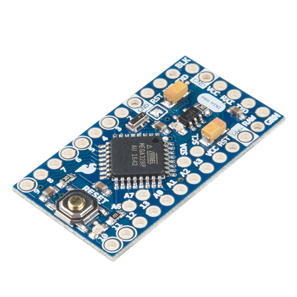
It's blue! It's thin! It's the Arduino Pro Mini! SparkFun's minimal design approach to Arduino. This is a 5V Arduino running the 16MHz bootloader. Arduino Pro Mini does not come with connectors populated so that you can solder in any connector or wire with any orientation you need. We recommend first time Arduino users start with the Uno R3. It's a great board that will get you up and running quickly. The Arduino Pro series is meant for users that understand the limitations of system voltage (5V), lack of connectors, and USB off board.
We really wanted to minimize the cost of an Arduino. In order to accomplish this we used all SMD components, made it two layer, etc. This board connects directly to the FTDI Basic Breakout board and supports auto-reset. The Arduino Pro Mini also works with the FTDI cable but the FTDI cable does not bring out the DTR pin so the auto-reset feature will not work. There is a voltage regulator on board so it can accept voltage up to 12VDC. If you're supplying unregulated power to the board, be sure to connect to the "RAW" pin and not VCC.
The latest and greatest version of this board breaks out the ADC6 and ADC7 pins as well as adds footprints for optional I2C pull-up resistors! We also took the opportunity to slap it with the OSHW logo.
Can't decide which Arduino is right for you? Arduino buying guide!
Note: A portion of this sale is given back to Arduino LLC to help fund continued development of new tools and new IDE features.
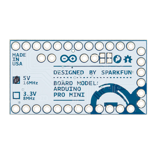
- ATmega328 running at 16MHz with external resonator (0.5% tolerance)
- 0.8mm Thin PCB
- USB connection off board
- Supports auto-reset
- 5V regulator
- Max 150mA output
- Over current protected
- Weighs less than 2 grams!
- DC input 5V up to 12V
- On board Power and Status LEDs
- Analog Pins: 8
- Digital I/Os: 14
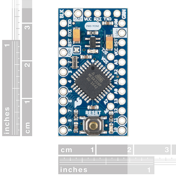
- 0.7x1.3" (18x33mm)
Arduino Pro Mini 328 - 5V/16MHz Product Help and Resources
Interactive Hanging LED Array
April 10, 2014
Learn how we converted 72 lightbulbs into an interactive LED array for our conference room.
LED Cloud-Connected Cloud
February 22, 2016
Make an RGB colored cloud light! You can also control it from your phone, or hook up to the weather!
Choosing an Arduino for Your Project
December 11, 2017
Examining the diverse world of Arduino boards and understanding the differences between them before choosing one for a project.
Adding a Timed Button to a Project
July 29, 2015
This tutorial will walk you through making a timed power controller for interactive projects. You will learn how to add an on button that will provide power to your project for an amount of time and then turn off again.
Reducing Arduino Power Consumption
November 10, 2016
A tutorial about different ways to reduce the current draw for your next Arduino project the easy way.
LED PomPom Headbands
June 14, 2017
Follow this tutorial to make your own light up PomPom headband! Try the beginner version if you are new to electronics or the advanced version if you have some more experience!
TB6612FNG Hookup Guide
September 29, 2016
Basic hookup guide for the TB6612FNG H-bridge motor driver to get your robot to start moving!
Using the Arduino Pro Mini 3.3V
September 5, 2013
This tutorial is your guide to all things Arduino Pro Mini. It explains what it is, what it's not, and how to get started using it.
The Uncertain 7-Cube
March 8, 2013
The Uncertain 7-Cube is a non-committal, less-than-helpful, but also entirely honest fortune teller. Simply ask it a yes or no question, give it a nudge, and the 7-Cube will dutifully inform you that it doesn’t have all the facts and doesn’t feel comfortable making a guess.
Flashing the Bootloader
This should only be done as a last resort
Most likely your board isn't bricked, unless you have done something drastic like modified the fuses. In which case, reflashing the board probably won't help you.
However, if you have no options left and want to try to reflash the bootloader with an Uno or RedBoard. Here are links to some tutorial to get you started:
- https://learn.sparkfun.com/tutorials/installing-an-arduino-bootloader
- https://www.arduino.cc/en/Tutorial/ArduinoISP
- http://www.instructables.com/id/Burn-a-New-Bootloader-Arduino-Pro-Mini/
(*Make sure to upload the ISP sketch to the programming board. Also, tie the VCC pin to the 5V pin of the RedBoard or Uno. This will set the chip on the Pro Mini to 5V without having to worry about any logic level conversion. Lastly, be sure to double check the board options you are selecting so that the Arduino IDE uses the correct bootloader hex file.)
Core Skill: Soldering
This skill defines how difficult the soldering is on a particular product. It might be a couple simple solder joints, or require special reflow tools.
Skill Level: Rookie - The number of pins increases, and you will have to determine polarity of components and some of the components might be a bit trickier or close together. You might need solder wick or flux.
See all skill levels
Core Skill: Programming
If a board needs code or communicates somehow, you're going to need to know how to program or interface with it. The programming skill is all about communication and code.
Skill Level: Rookie - You will need a better fundamental understand of what code is, and how it works. You will be using beginner-level software and development tools like Arduino. You will be dealing directly with code, but numerous examples and libraries are available. Sensors or shields will communicate with serial or TTL.
See all skill levels
Core Skill: Electrical Prototyping
If it requires power, you need to know how much, what all the pins do, and how to hook it up. You may need to reference datasheets, schematics, and know the ins and outs of electronics.
Skill Level: Competent - You will be required to reference a datasheet or schematic to know how to use a component. Your knowledge of a datasheet will only require basic features like power requirements, pinouts, or communications type. Also, you may need a power supply that?s greater than 12V or more than 1A worth of current.
See all skill levels
Comments
Looking for answers to technical questions?
We welcome your comments and suggestions below. However, if you are looking for solutions to technical questions please see our Technical Assistance page.
Customer Reviews
4.6 out of 5
Based on 139 ratings:
4 of 4 found this helpful:
My favorite and most useful Arduino
You get everything a larger UNO has but it is a super small form factor. Using this in projects where space is a factor is a must. I bought the SF pro mini kit that comes with the FTDI board and some other things like lights, buzzer, etc then I bought 3 separate Pro mini.
One bad thing about them is the pads are very sensitive so if you solder to them and you mess up it can be very hard to remove the solder without damaging the pad. I lost my left TX0 pin on one board.
4 of 4 found this helpful:
More that just an atmega328 breakout board
This board will end up as the controller in the front panel of a little QRP transceiver I'm building for the 40 and 20 meter bands. It will control an AD9835 DDS VFO among other things (should be enough space in the flash to code a CW keyer as well). I would have normally used an ATmega384 but this board is smaller than the 40 pin package of the '384 and is 'ready to go'. I'll add an 18pin i2c i/o expander chip if needed. Great little board when you need a micro controller for a project, and it's smaller than using a DIP package IC, but as easy to wire up. (only gripe was having to solder the i2c pullup resistors on the bottom).
Well after all this time, I just discovered that the jumper for the regulator was actually the solder blob near the regulator, not the trace under the I2C pull up resistors. Wish you guys would have identified that. So I removed my comment about that, and added a star to the review.
BTW, If you want to run the 5v part at 3.3 volts, you can, unsolder that blob, and provide 3.3 volts to the VCC pin. Then reflash the bootstrap and the fuses so that the divide by two clock pre-scaler is enabled to run the board at 8mhz. This way you don't have to replace the crystal or the voltage regulator. You'll have to modify the bootstrap, recompiling it with the CPU set for 8mhz, and adding the logic to set the clock divider. Also need to set the divide by 8 fuse so that you don't overspeed the cpu clock before you can execute the code to change the divider to 2.
3 of 3 found this helpful:
Extremely useful Arduino board
I've used it a couple of times and the low price, small size and thinness of the board makes it extremely useful. I would however have liked a beefier voltage regulator. 150 mA is too low for many of my projects which means I have to stuff in an additional voltage regulator somewhere in my otherwise tiny project.
1 of 1 found this helpful:
Easy to use and works well
Unlike my understanding of Sparkfun's write-up for the Pro Mini, it works fine to upload programs with just an FTDI cable, don't need the special FTDI adaptor. It would also be helpful to explain how to install the pull-up resistors onto the solder pads provided for SDA and SCL. Can we buy the tiny resistors that are needed, and just how are they installed onto the solder pads?
Hello!
Those type of tiny pads are typically soldered to through surface mount soldering. We've got some guides available here: https://www.sparkfun.com/tutorials/category/2 that go over it, though you can do it with a wand too if you're patient and have a steady hand.
In regards to what type you would want, you would wanna go with a 0603 form factor SMD chip resistor - there are many around that you can choose from if you google 0603 resistors - I would say you probably want to check what device you're using to double check what value of pullup they want, but 10k is not that uncommon.
4 of 4 found this helpful:
Great simple embedded processor
I must have a dozen of these. They are my go-to processor for simple projects. (For more serious applications I use ARM processors.) I have used them for a health monitor, sun tracker, gyro calibration table, motorized rotation stage, furnace monitor, and other projects. My only wish would be to have an optional true RS-232 output, but I make due with an external converter.
6 of 6 found this helpful:
A great product for small spaces
I've built a lot of projects with various versions of Arduino. This one takes the cake for small size, however, and still has all the I/O leads. Works just like any other '328 based Arduino, just tiny (and thin – the circuit board is thinner than the usual 1.6mm ones). Pins on the end let you power/program it with an FTDI cable or FTDI Basic, or power it. I just solder a 6-pin header on there, and wires on the I/O pins for whatever I want.
2 of 2 found this helpful:
Second item on my "Things I need infinite of" list.
First item is, of course, breakaway headers.
These things are fantastic, and I've integrated them into so many projects. They've got everything you could need (Except a USB port... but there's a FTDI adapter for that). Plenty of pins to utilize. Low-profile. Built-in power regulator. And it's $10.
1 of 1 found this helpful:
Great little powerhouse
I've used a knock-off of this true Arduino and have found that the components and manufacturing quality of the knock-off were sub-par to this little gem. My ONLY complaint is the difficulty in un-soldering the jumper to isolate the on-board regulator. If this were on the backside of the board (wasn't it at one time?) it would be so much easier to un-solder with less chance of disturbing other components.
6 of 6 found this helpful:
Power in Small Packages
This is my go-to board for pretty much any electronics project. Working with it is almost an unnoticeable difference from the UNO or RedBoard (minus size, of course). My only grievance is that you have to solder and desolder wires to test with it instead of being able to use jumpers like on a bigger board, but that's my lazy side talking. Soldering makes for a more permanent connection than the female headers on the RedBoard or UNO (non-permanent connections are a pet peeve of mine), and honestly, they're so cheap, I just got another one and tossed on female headers so I could test with it before I soldered my final product together. Without a doubt, this is my favorite product Sparkfun sells.
4 of 4 found this helpful:
This fits the bill
I love this board. It's tiny, it's powerful, it's inexpensive, and I can design a PCB using this part as it is in the sparkfun EAGLE library. Right now I am in the process of designing a Tachometer around this board, and a serial 2x16 LCD. The tachometer is for a Honda XR650L dual sport bike. I have the board layout complete and am about ready to send it out to be made. When the tach is completed, I will post a video of it.
5 of 5 found this helpful:
Great buy
Great for the breadboard, and semi permanent/permanent projects.
Need to solder on headers, but that's expected and keeps the form factor flexible.
But - my only gripe is that A4 and A5 (SDA & SCL for I2C )are not broken out to the edge. When I have it on a breadboard, I have to solder on headers to the top. It's a tight space, and extra wires coming out of the top is messy. A lot of my projects are using these pins, and the slight increase in board length to accommodate these two pins would be well worth it in my opinion.
1 of 2 found this helpful:
My favorite Arduino board
It's small, it's inexpensive, and it does everything you would expect from an Arduino.
Great
Well made.
Small Power
I've grabbed a few of these, and a few osepp ones as well (older version)
They are nice to add simple controllers to just about anything. The concepts can be tested on a uno and loaded on the Pro Mini seamless and easily soldered to a solderable breadboard. This takes a project that spans a testing table to pocket size in minutes... well ok... maybe an hour.
Easy Setup with Eclipse
I prefer to use Eclipse IDE for most of my programming (HTML, PHP, CSS, JS, C, C++, Java...etc). The AVR plugin for eclipse works really well for the Atmega 328(P) boards. Easy to set up Static Library for the chipset, then focus on the int main(void) part of the application and quickly deploy the application to the Mini or Uno.
I HIGHLY recommend getting the FTDI Basic Breakout (DEV-09716) and/or the FTDI cable (DEV-09718). Both work wonderfully with this board. Some soldering may be required so pick up a few Breakaway Headers (PRT-00116).
Solid little workhorse
These are a great little board. Plenty of power and really small size. They just work!
Excellent product
This tiny thing really helped out when I needed it most. I'd like to see it sold without arduino bootloader pre-loaded if it meant it could come in just a bit cheaper though. All in all, happy.
Inexpensive and works great!
Bought two of these along with the FTDI Basic Breakout. Installed sockets on one to allow me to make quick connections with 24 gauge solid wire for general experiments. Used the other one to build an Iambic CW Keyer. Going to order a few more to keep on hand for future projects!
Easy!
Very simple to set up, had wiring and code up and going within an hour of opening the package.
Exactly what I needed
Small and easy to integrate into projects where I need a micro controller. Saves me from soldering more smd stuff. Just all around simple to use.
Tiny, Useful, Economonical Uno on a diet.
I like this little board because it is very similar to the Uno with some extra analog inputs and a little less power supply. It counts pulses, watches sensors, directs NeoPixels, and does a lot of other stuff. I program then as little I2C slaves to gather and average readings for my gravity sensor experiments. It's small enough to fit into my pirate chip plush project, watch and post process GPS data, and is quite small. It's already in the Arduino UI and just works. Aside from a few K more RAM, what more could one ask of an economical, cool looking, well maid board?
Great as
Great product. Compact. Inexpensive (due to MINOR hassle of "having" to do USB off-board. Do I want idle USB ciruits on deployed Arduinos? No!)
I've done KiCad .lib and .mod files for those who want to put an Arduino Pro Mini on a PCB of their own design. Free.
http://kicadhowto.org/LibLib.htm
The small size of the Arduino Pro Mini reduces the expense of the PBB you are making, as there is little board area under the Arduino.
Excellent
Great option for my embeded arduino projects. I have used it on several wireless and control applications.
The same performance and capabilities of an Arduino UNO in a much more compact package. So far everything is great
Extremely useful Arduino board
I've used it a couple of times and the low price, small size and thinness of the board makes it extremely useful. I would however have liked a beefier voltage regulator. 150 mA is too low for many of my projects which means I have to stuff in an additional voltage regulator somewhere in my otherwise tiny project.
Great little arduino board
Compact and efficient, uploads easily with FTDI breakout. Great way to save space in your project.
Perfect for permanent hacks
I had an Arduino Nano tied up on a breadboard for the better part of a year as part of an FSR endstop detector on my 3D printer. I wanted to get the mess of wires and proto parts off my desk, so I flashed one of these with the project, soldered on some headers and pullups, cleaned up the wiring, and hid it neatly under the printer.
My only complaint is that it's fiddly to temporarily connect to the UART for programming without soldering down a header. It would be really nice if staggered holes were used here instead. In my case, where I'd already proven the code out elsewhere, test clips were sufficient to get the job done.
Great
Small, Lots of i/o.
Great device for building a compact project!
Minimal design approach in a small package, which fits my needs perfectly. The large, positive action reset button is a nice feature too. Plus you know when you purchase from Spark Fun that there are no counterfeit components on the board.
0 of 1 found this helpful:
Are you kidding, don't event think about it
OK, don't get me wrong here but I don't event think about this part. It is what it is. It works, its cheap, (have a few hanging around). I am working on a project that took a lot of RAM and Flash. Hey, make it dual processor, because I have A FEW LAYING AROUND that costs $10 EACH!
Perfect for so many project at the right price!
I have so darn many of these in use right now. The one time purchase of an ftdi board and off you go!
Why use anything else?
This is a great little machine. It's cheap, small, and powerful. You could attach headers to it for prototyping, but I usually develop using an Uno and then replicate the circuit over to the Pro Mini. It's that compatible.
great board
This is a great board, and at a suspiciously low price.
0 of 1 found this helpful:
Good Stuff
It works! It does what it should.
I make a 'spot' for it on my pc board and it saves space and time.
Things are good these days. If I had these years ago, Just imagine.
Thanks. Sparkfun is good too. I always look at you for my first bom. Thanks.
W R
Best ardunino for inbeded projects.
So you have gotten your feet wet and learn the basics, and now your ready to make a useful project using the Arduino, this is your guy. Low cost, small package makes it great for those projects where you want to mount the Ardunio permanently. Only thing I would change is ditch the reset button and charge 50 cents less,.
Great for smaller projects
If size is an issue, this is a great product to use. Only thing I wish it had was a 5V output since the sensors I used required a 5V regulated output. This can be fixed by using voltage regulators, but it was a slight nuisance. So, 4 stars instead of 5.
Hi! The VCC pin on the board is a regulated output pin. On this board it's a 5V regulated line. The regulator is rated for 150mA.
An ideal size for an Arduino compatible micro!
little larger than a large postage stamp with 14 digital and 8 analog ports, this micro can fit almost anywhere.
Easily my favorite SFE product.
The Arduino Pro Mini is cheap, tiny, and easy to implement. I consider this the best option for Arduino-based projects (as long as you know what you're doing). Onboard voltage regulation is a huge plus.
Love it.
I embed these in all kinds of models I build, it really simplifies the lighting. Instead of running dozens of wires to lights in the model, I just have to run power to it instead.
Great Arduino
Perfect for my applications and very compact.
Great For Prototyping
I use the ATmega328P on many of my own PCBs, and this board is perfect for prototyping before committing to a board design. I'm able to program it with either the FTDI Basic (DTR) or a 5v FTDI cable (RTS) using the Arduino IDE. The note in the description on auto reset not working is somewhat misleading; might be helpful if there was a little more info on this. My only complaint is the A4 & A5 pins aren't brought out to the edge, and they're not even on the same .1" grid pattern as the edge pins. Wouldn't mind the extra 0.1" board length to bring these out. I do like having the solder pads for I2C pull-ups on these pins right on the board.
Excellent product
Allows full automation of systems while remaining extremely space efficient. Perfect for mounting onto a small protoboard
An excellent product at an excellent price
The Pro Mini 328 has all the IO pins of the full size Arduino Uno board, and the tiny form factor makes it perfect for projects with cases that are too small for the full size board, plus it's only a fraction of the price. You'll need to solder wires or pins to the board and use a separate FTDI board to program it, but that's not a problem for experienced experimenters. Also, you'll lose the ability to stack standard shield boards on it. But, If you're using this board as a controller in a project that will only be programmed once, and has to fit in a very small space, then you don't want to pay for a FTDI circuit on every board. Unless you're a total novice, or need to add shield boards, then this board is a great alternative to the full-size Arduino Uno board.
I love the small footprint and slimness, which make it so easy to incorporate in a variety of projects.
Perfect. Easy Microcontroller in a small package
I used to program PIC microcontrollers, but have become irritated by the poor compiler. It actually inserts junk code in unless you buy the high end version. This is nothing like a PIC. Its faster. Has plenty of memory. its just awesome and I couldnt ask for more. I put a header on it, plugged it into the USB->Serial converter and started programming.
And its small! And its cheap! This is now my #1 go-to microcontroller.
Great little device
And I make sure I have a few on-hand. I've used these in various projects now and they just make it easy - do a quick HW design, hook things up, and then add a few features purely via SW as enhancements become apparent. The ability to source, as well as sink, enough current directly to drive LEDs is really handy.
Easy to connect to, inexpensive, and has the functions I need
This is much smaller and less expensive than an Uno, so can fit in a hand-held enclosure, yet has all the functionality I need. I can read external sensors and display the results on an LCD display via the I2C bus. Plenty of inputs to connect a keypad or pushbuttons. And using an FTDI friend with a USB cable I'm able to program it without any problems at all. I now use an Uno for prototyping, then port the program over to a Pro Mini to build into my enclosures. Thanks, whoever came up with these... Keep up the good work!
good condition, a bit confused
After a while i figured it out, but id didn't realize i had to solder the pins on myself, but that was justfrom my lack of experience.
This is a great product for completing a project created on a full sized arduino on a protoboard. I don't care for "shields" as it seems to cause a lot of extra physical connectors and such... I'd rather take a solder-proto board, a Pro Mini and whaterver else is needed and build it up. Make for lower cost and more compact projects - but does take more time. If you can live without headers - this is THE Go-to Arduino board - and I think there is a similar "Leo" version. Also - the new pinout-PDF for the Pro Mini makes it even easier to use. BUY TIME! :-)
Works great
I made the mistake of trying some knockoff version of this first that fried itself when I hooked it up to 12V. The genuine article works great and is perfect for permanent embedding in small projects.
My new favorite Arduino
I had no idea that so much awesomeness could fit into something so small. This thing rocks. I've had no issues with them at all.
-Edit: The only major issue I've come across is that it does not do so well being powered by a battery pack any larger than 8.4V. Anything over that, and the teeny-tiny 5V regulator on the board starts getting VERY hot. Be careful for this!
Best for small projects!
I'm still fairly new to the Arduino, but I had a few projects I wanted to make more permanent without dedicating an Uno to each one. This was exactly what I needed. It's small, powerful, and easy to program with the SparkFun FTDI basic breakout.
Great little board
Works perfectly
The Arduino Pro Mini is a Fantastic Option
Fantastic option when space is tight and you want a lightweight microcontroller. I used mine for a model rocket flight controller that ensures electronic staging only occurs if the upward trajectory is near vertical and the rocket is stable. I also built a remote controller for shop vacuum system around the Pro Mini. What a great product! Thanks SparFun!
Excellent Board. You need to buy 10.
Love this board and use it all the time in projects. Right now I've got one on a breadboard with an ftdi basic hooked up. It's so fresh and so clean. A+++ would buy again.
Embedded Prototype for Inclined Plane Rectilinear Motion
This microcontroller is using its size and simplicity to implementation and development of a didactic prototype for measuring acceleration, speed and time in experiments to demonstrate Newton's three laws of motion using rectilinear experiment. This work was presented in Mexico as an educational prototype, but was not well appreciated by the entity, who severely critical as the normal force is measured, nevertheless, the idea yet been implemented in the laboratory to demonstrate that the normal force is a conservative force.: http://somi.ccadet.unam.mx/somi30/programa.php?id=3
Compatible, flexible, and tiny
Compatible: I use these boards after I have done my prototyping with an Uno or RedBoard and I'm ready to build my project in a more permanent fashion. Flexible: No, you can't bend it, but you can solder (flexible) wires, or male or female header connectors. I use male header connectors on the bottom side because then I can simply "plug" the ProMini into the board it's interfacing with, which is frequently just a perfboard. Plug and play. Well, plug and solder, then play. Plus I install a 6-pin male header connector on the top side for interfacing with the FTDI Basic Board (DEV-09716) for programming. I can upload the initial code during construction, but easy enough to plug in the FTDI Basic if I wish to upload new code later. If it needs to be low profile I install a right-angle header connector and I can plug the FTDI Basic in from the side. Tiny: Well, that pretty much speaks for itself.
Love the Pro Mini
For me the best thing about the pro mini is it fits on the bread board. I can easily prototype and then fit the little board into a project.
My only complaint is that A4 and A5 are not on the outside. They are the I2C pins, and it would be nice if those came out to the side in preference over 2 of the other analog pins, as they can also double as analog pins.
It'll always be my first
Exactly what you'd expect it to be. This little thing is what I used for my first permanent arduino project. Failed to order the FTDI breakout cable, but I found instructions online to program it using my Uno.
Small yet powerful
Perfect compliment to Raspberry PI for data acquisition
great job with the shrink-a-nator
When your project (or skills) are wanting a very small board, this is the way to go! I also like not having to have USB on board; the programming cables are just as convenient and that leaves fewer components to fail in the project.
Arduino Pro Minis are Pro!
Very easy to use Arduino platform with a small form factor. Cheaper than an Arduino Uno and easily fit into a breadboard with headers. Great breakout!
Perfect form factor
I recently purchased one for a project at work that was very space constrained. Then I immediately bought 2 more. So inexpensive that I don't feel bad about soldering only the headers I need on it (soldered the programming header on at 45 degrees which was just right for my application). So now I have 3 in 3 completely different configurations. Love this thing.
I use it for all my projects.
Inexpensive, easy to program. Small footprint. 16 mhz. Use it for everything except when I want a full arduino footprint.
These are an inexpensive powerful solution.
I have used several of these in projects and they work great. I even made a footprint for my own PCB to install this board rather than lay my board out for the processor only. I have one installed in my golf cart to monitor the batteries and display date, time, battery volts, state of charge, and MPH.
Impressive
I pretty much only use this version of the Arduino now (for everything new). Unless you need the gazillion pins of the Mega, this little board can either plug into a protoboard, or another board designed to receive it, or can be used standalone, giving me flexibility beyond what an Uno offers.
With the USB converter board that sparkfun offers, it's absolutely as easy to use as any other Arduino and way more flexible. And it's ten bucks. What's not to like?
Just what we needed
Fast efficient service, works great.
Easy to use and small enough to fit almost anywhere.
I have used a few of these now. Cheap enough to use for almost anything. Small enough to fit almost anywhere.
My last project used one as the heart of a controller to run all of my Halloween animatronics. The next one is destined to display Christmas cheer for all to enjoy. Once populated with a few headers they are easy to program with the SparkFun FTDI Basic Breakout - 5V
Pro Mini is just about the ultimate arduino
I really like the Pro Mini 5v/16MHz.. That is why I now own about 20 of them.
I do not ever want to see them on your obsoleted list!!!!! One of the most important aspects of any electronic component is consistency in availability. If you ever quit making the Pro Mini, especially the 5v ones, I will really be pissed!!!!!
There is only one thing that could improve the Pro Mini and that is the physical footprint. The ultimate arduino would be to make a pro Mini with the exact same electrical schematic minus the serial chip etc. but have the same footprint as the Arduino Nano with two rows of 15 pins.
Nyle Steiner
A little Workhorse
I have used the Pro Mini for a number of projects, both at home and at work. It has worked well and kept the size of the enclosures very small. My bosses love the price, as well! It's made me a hero.
Small and inexpensive
If you need an Arduino in a compact package, this fits the bill.
Like someone else mentioned, getting the I2C lines out to board edge would be very useful.
Plant Moisture Sensor
The low power draw and small footprint should make this board well-suited for my application as a plant moisture sensor.
I'm still reading up on methods of operating the Pro Mini with minimal current draw. One suggestion is disconnecting the LEDs and regulator. The addition of removable jumpers on the PCB would be helpful.
I tried powering the unit using the RAW power connection. Unfortunately, my unregulated 9V supply whose no-load output was about 14V, enough to damage the Pro Mini. Having learned my lesson, I bought one of Sparkfun's regulated supplies which solved the problem.
I also had occasion to talk with Sparkfun's Tech Support which was very knowledgeable and helpful.
It works as expected
Nice small size, easy to work with.
Big surprise, small package
I own a couple Arduino Uno's and was never sold on the Mini's. I bought this one for a robot project and what a big surprise. This thing is as capable as its bigger counterparts. I will definitely be getting more of these for future projects. I'm very happy with the performance and ease of use. I highly recommend giving these a try.
Versatile
We're a radio station still playing classical music from CD's. Transferring the audio to HD is easy - it's the metadata from the liner notes that is a problem. Broadcast CD players are almost extinct and standard CD/DVD players have no front-panel controls. We've compensated by buying inexpensive DJ-type CD players and modifying their functions to do what we want using an Arduino. We've added external start-stop inputs and defeated the "snooze" function that put the machine in standby if it was left in cue for too long. Great product!
Great for small board packaging
I am utilizing a Pro Mini to control a cooling system I have designed for my Senior Design Project at California Polytechnic State University: San Luis Obispo. There I study Mechanical Engineering with a Concentration in Mechatronics. My project is a Prosthetic Socket Cooling System for an Afghanistan war veteran who suffers from overheating due to wearing four prosthetics. I am also in the works in designing my own printed circuit board to house all of the components in a small package to be worn on the prosthetic. Sparkfun has been a fantastic avenue of information and products to facilitate project progress and completion.
nice and small form factor
I use an Arduino UNO with the 328 removed as the serial usb interface. So I can bread board with the UNO then do final with the Pro Mini
Not too bad
Bought this to make the Hatermatic project. It worked for about a year, but I tried updating the code and something went wrong with the bootloader and it would no longer accept code. Rather than buy the stuff to fix it, I just bought a new one of these. Works good.
Great for small scale
I used this board in a project that was outdoors. I loved that it free'd up space to use for other items. I mounted it to a breadboard with female headers. Whenever I want to update a small piece of code I just pop it out. It always me to program inside the warmth of my house.
This is a great board
The is a great little board. When you don't need the functionality of a full Arduino, this is perfect. It's small, is available in 3.3 and 5 volt versions and is very inexpensive.
Great board
This Arduino Pro mini is working fine
Great! But don't break it
Works great! I buy them for the price.
perfect for neopixel luxo lamps for christmas
the right amount of IO. easy to program. and cheap!
Mini Mighty
Picked a bunch of these up during a discount - they can't be beat for size, and processing power in that space.
No more LLCs
I do a variety of projects and each have their purposes. I tend to want to standardize on hardware wherever possible; sometimes this means including some LLCs to go between 3.3v and 5v which expands my payload (not a good thing when adding electronics to toys).
Having a 5v option for the Pro Mini helps alleviate having to add LLCs for certain peripherals; this allows me to choose which version of the Pro Mini. Which is nice for me.
Great little arduino!
Once you've mastered the UNO go ahead and get the Pro Mini! Make your projects smaller and neater by using wires soldered to this. I got mine on Arduino day, I've been using Pro mini from another source and this definitely has better quality!
Where's the pin headers?
Product was fine and at a good price on Arduino sale. I like Sparkfun stuff. But, I've got these from other companies and they included pin headers? Maybe THAT was fluke? Throw a couple rows of headers in the plastic bag next time......please.
use it for low-power applications
I'm using this for a simple weather station with DHT22 and BME280 sensors and a Sunny Buddy solar/lipo supply. It also needs a buck-up controller to power a 5-V board. It requires more work to set up because it is not compatible with standard Arduino shields. But, it is not hard to do on a breadboard -- just solder headers along the edge. The SCL/SDA pins require separate wires to the breadboard. It requires less current than an Arduino Uno or RedBoard. I use the Narcoleptic library in my code to reduce the power requirements even farther. You need an FTDI module to communicate with a computer's USB port.
The only problem we had was that the display we was driving was a 3.3 volt device. It took out three of the pins driving it. We added a 680 ohm resistor in series. Now all is good.
The original Pro-Mini!
Small foot print, 8 analog inputs, low cost! What's not to like? It's not the most convenient development system as you need to isolate d0/d1 while programming but if you want to stamp out a lot of inexpensive nodes or do something that doesn't need to communicate, the package is powerful and the price is right. Just plug it into your circuit board design and save a bunch of dedicated logic.
Great product at a great price
Was the right size at the right price with all the functionality I needed.
Great product, awful shipping
I bought this to use in a project that I had prototyped with an Arduino Uno. I had questions about the optional pull up resistors, which their support team answered quickly and accurately. The helpful and informative web site pointed me to everything I would need to successfully use this remarkable little gem. My project was a success. This is the product I will reach for next time I need an Uno class microcontroller.
But the shipping was awful! I was initially thrilled to find an innovative electronic supplier just one state away, as my previous favorite was on the east coast, charged too much for shipping (often as much as the product), and took a week to get here. I was excited to be able to get stuff quickly. Imagine my disappointment to discover that SparkFun's shipping was even worse. They didn't get the order out the door for three days, which their web site says is normal. Their most reasonable option was FedEx smart post. So, after several days, I moved on to my next project, which I ordered from a company in the Midwest. I ordered on Saturday, received an email on Sunday saying it shipped. They charged me $3 to ship it via USPS. Both orders arrived the same day.
I2C bus capacitance out of spec, causing I2C to not work
The I2C bus capacitance on SDA and SCL is around 4 uF (4000000 pF). Spec is <10 pF, and the total allowable on the bus is 400 pF. Accordingly, it is impossible to pull up the lines fast enough for even low speed I2C (100 kHz) communication. I tested 3 samples, all had this problem.
Sorry to hear about the issues with the pro mini's. Have you contacted our technical support department at Techsupport@sparkfun.com - they're usually pretty good about helping figure out issues like this.
perfect
its better than the old design because there is good description on the board
Arduino mini
I ordered 5 of these. One did not work. Had to order 2 more just incase it malfunctions.
I've had to update my rating, customer service reached out to me and was very helpful and refunded me the malfunctioning board. They are very interactive and easy to reach. I appreciate the great service over there.
I'm sorry to hear that! We try to make sure no bad boards go out in orders but sometimes one gets by us. Please contact our tech support team at techsupport (at) sparkfun (dot) com and we can help you with this.
Disappointed / Labeling Issues
I know what I ordered but the boards are not marked. There is clearly a place to indicate on the board what they are, but no-one bothered to mark them. It makes me question whether they are 5V or 3.3V, 8MHz or 10 MHz or 16 MHz. There are enough variables to evaluate without having a clearly marked product that I can depend on.
Always reliable, great design
These little guys are just great for remote nodes tested on a breadboard.
A handy little gadget!
Easy to solder pads. Easy to program via FTDI by Atmel Studio(V7.0) and Arduino IDE.
A very flexible little module - I've soldered pins to 3 of the 5 that I've bought and left a couple in their little packets for some as yet unknown future project.
Work great for my projects very happy with them. TinVu
This is my favorite the Pro mini
It's compact and works every time It's also a great field swap board you can touch up your program at the shop and then install quick in the field .
Dave
Great little chip.
Very durable with lots of digital pins. Don't understand having 3 grounds though. Could have put SDA and SCL on two of the ground pins. Otherwise, it's a great chip with lots of room for code.
Worked as expected. Good quality
Used these in an wearable application driving 16 APA102C LEDs (Lumenati boards). All 6 units worked perfectly. Build quality was good with no noticable solder flux anywhere.
Works great even after sitting in water
I'm using my pro-mini as part of a water quality data logger/sensor (electrical conductivity and temperature) at a mining waste reclamation area. The entire package (sensor, data logger, and enclosure) sat in a mountain stream for over a week. The enclosure didn't hold up as well as planned; it leaked and the data logger sat in stream water for the last 4 days. Still works after a bit of freshening up with a hair dryer.
My Favorite Little Controller
These things have become my "go-to" for projects; I prototype on my Uno, and then move things over to this tiny little $10 board. I've used 5 or 10 of thiem, over the last few months, so far their record is flawless! Highly recommended.
I love these little things
The Uno is great for learning, but not so great for doing, due to its awkward footprint. The Pro Mini is perfect for embedding in projects. I use it for about everything.
Handy little gadget
I pick up a few of these things every time they go on sale. I like to keep a few on hand in case any little Arduino project comes up. I have used these to build a large format count down clock for a FIRST Robotics Competition team and a miniature replica of the Enterprise's warp core.
It is really handy to prototype on an Uno and then just move everything to one of these to fit in small places. The on board regulator can't handle much beyond the board itself. But that is not a big deal to me.
Too easy
to try anything else. For small projects, I always think of this board first.
Stable ProMini
ProMini worked right off the bat. One issue is in the board design... the SCL solder pad is dangerously close the micro chip soldering pads. Otherwise seems to be performing well (acting as an I2C slave).
My favorite arduino for breadboarding
This is a great Atmega328 board. I have several, and am ordering more. With headers added, it plugs into a breadboard, and having the IO out on a breadboard makes it much easier to prototype with thn say an Uno. Only one minor complaint: I wish it was 0.1 or 0.2 inches longer, with additional in-line pads for SCL and SDA. My workaround for that: I cut the headers two pins longer, with the extra pins hanging off the end past the reset button. Then wire those to the additional pads to bring SDA and SCL (and A6 and A7) down to the breadboard.
Simple but powerful
I'm a big fan of the Mini. It's simple to use, plenty of processing power for most tasks and the form factor is great.
Go-to little AVR brain
if you're too stubborn to use anything but AVR, and don't need shield compatibility, no reason to use any board other than this.
(no sarcasm; this is genuinely my go-to)
Always one in my stash
This is my go-to unit. Lately i've made two gear door sequencers for radio controlled aircraft. I always keep a spare ready for the next project.
Perfect format for my projects
I use these boards for nearly all my projects - small form factor and enough I/O to get the tasks done. Typically used on my own custom PCB that readily wires the Pro Mini, a RTC board and up to 4 stepper motor controllers along with headers for 4 Hall effect sensors, 4 switches and a couple of LED indicators.
Selecting board
Hi, I didn't find it anywhere in the documentation on sparkfun, but I wasn't successfully uploading "Blink" to the 5V/16MHz board with the IDE "board" option set to Uno or Uno Mini; apparently buried somewhere in the official Arduino docs (OK, not THAT deeply) it says to select Duemilanove, and once I set it to that it uploads just fine and I am the proud and happy owner of a blinking green light. Did I miss something in your docs?
Good but not great
This is a great board if you only have one thing to do. It just does not have enough speed to do more than one thing. I like the size and the easy programming with the Arduino IDE. The only really bad thing is the onboard 5 volt regulator which is pretty close to useless. If you have any extra load on the 5 volts and you put 12 volts into the board it will just blow up and smoke.
Absolutely fantastic product.
The pro mini is my "goto" microcontroller. I usually solder header pins then use in wire wrap perf boards.
Arduino Pro Mini is great
He helped me in my projects, it is small, compact, just great
Too stinking kool!
Great little board with big dreams. Lots of power in a very small package. Love working with this board. Whatever will I build next?
0 of 1 found this helpful:
it is an arduino
A built-in level shifter would be awesome
Perfect for small projects!!
Just ordered 3 more. The size is perfect for small projects including home automation. Screwed up meant to give 5 stars!!
Great Arduino, Great Price
It does exactly what it should. Makes it easier to put an Arduino in a permanent project.
0 of 1 found this helpful:
My computer wont recognize it.
I downloaded all of the necessary drivers except it wouldn't recognize the Arduino. I tried switching the board in the tools section and I tried changing the COM port but nothing worked. It seems like a great board that would be great for low-profile projects but I just can't get mine to work.
not bad
decent price, compact size. but the arduino settings for this board didn't work at all, had to use the 328p settings included with the arduino ide.
Sorry to hear that. It's an odd issue, possibly your board was booted with the wrong version of the bootloader. Let us know if this is an issue and we can help you out.
Neat device
I bought these to use in an RC transmitter design obtained elsewhere. I was not aware of them or their capability at the time.
It worked out great and really got me interested in the microprocessor and the programming of it.
Easy to learn and works as advertised. There is lots of similar projects and help available.
Highly recommend them.
Great for teaching labs!
These little guys are great for teaching how to program in arduino and build sensor and control systems.
I usually supply unregulated power to the boards, but I connected it to the raw pin.
As I understand it the D11 to D13 pins also serve as MOSI, MISO, and SCK for SPI, unlike say the Uno or RedBoard which have a dedicated SPI header. Is any hardware or software reconfiguration required for SPI on the Pro Mini or do the SPI functions "just work"?
Since both the Pro Mini and the Uno/Redboard use the ATMega328 the pin usage is the same. While the Redboard does bring out the ISP header those pins just go to D11-D13 (but on a Lenardo for example they would go to different pins, making that port consistent). In other words since D11-D13 are the SPI pins on the ATMega328, those are the correct pins for the Uno/Redboard as well as the Pro Mini, and so should "just work".
Any chance this has any PWM pins?
Edit: found the answer at https://www.arduino.cc/en/Main/ArduinoBoardProMini
Yep, it is an ATMega328 so it has all the same pin functions as an Uno (with the addition of A6 and A7). The 6 PWM pins are circled on the board (thin white line around the pin hole).
Not sure if anyone has brought this up already.....is there an Ultiboard/Multisim footprint for this somewhere?
Just to ask, how do I connect an external power source (Barrel Jack) to this board?
There are no pads to solder a barrel jack directly to on this board, but you could connect one with wire to the RAW and GND pins. Check the hookup guide for more details.
Can I program the 5V Pro Mini with a 3.3V FTDI cable?
That should work fine. The Pro Mini will only be running at 3.3V which for 16MHz is technically out of spec, but does tend to work.
I commend your use of a proof quarter for the scale reference photo.
I'm wondering if someone has an answer for this: My sketches run a little slower on the Pro Mini than they do on the UNO, and I'm not sure why. Normally it wouldn't be a significant drop, but I'm sending and receiving A LOT of signals per second between multiple Arduinos via serial and infrared light, so even a tiny reduction in speed makes a big difference. Where the UNO performs flawlessly, I'm getting some missed signals here and there with the Pro Mini. Shouldn't the Pro Mini perform exactly the same as the UNO? Maybe it has to do with how much constant power it supplies to the ATMega? I've noticed that the 5V regulator gets VERY hot on the Pro Mini if you give it more than 8.4V, which makes sense because it's so small. Any ideas?
and yet you can get arduino nano with usb onboard for around five bucks shipped on ebay.
How can I hook up a transmitter or receiver to this? I’m looking for the receiver to then control one DC motor and a servo motor (making a RC car). Does anyone know a helpful thread, page or comment that I can use to educate myself on this type of stuff?
I know you've only just updated these boards, but may I make a suggestion for the next version?
For my battery-powered projects I've been modifying my ProMini boards by cutting the trace from the voltage regulator. See this picture. This reduces the minimum current draw from ~1mA to ~1uA in power-saving modes.
It would be really nice if the next PCB revision had this connection on solder-pads. That would make the low-power modification easier to do (and undo).
I just received my Arduino Day order, and noticed that you've made exactly this modification (except that the 10uF smoothing capacitor is retained when the regulator is disconnected).
So, thanks Sparkfun! You're great.
Thanks for the kind words Tim. We were planning to revise this design to include proper 0603 footprints for a while. When I read your comment I thought, "hmmm... There might not be space, but I'll give it a try." I'm always up for a challenging layout :) Hope your low-power projects are going well!
That's awesome - I second this.
what is the voltage of your battery,3.7v? Are you connecting the battery to Vcc or VRAW? Are you also cutting off the status led? After cutting the trace, are you driving the Pro mini with 3.7v? is everything working fine under this voltage without regulation?
In various projects I use a 1.5V battery boosted to either 3.3V or 5V, depending on whether I'm using an 8MHz or 16MHz Arduino and what voltage the other parts of the project require. The trace-cut disconnects the regulator and the power LED, so you need to provide power to Vcc.
Can you let us know what connection you're severing on the schematic when you do this mod? We've been using a lot of these boards for a project, and would love to reduce the standby current.
With the regulator and LED disconnected the only component drawing power is the ATmega328. The datasheet claims it draws less than 1uA in the power-save and power-down modes, though my multimeter can't accurately measure such a tiny current. With the CPU running you can save power by setting the fuse bit CKDIV8 which reduces the clock speed. But usually it is better to leave the clock at full speed, which allows you carry out your task more quickly and spend less time outside the power-saving mode.
With the regulator and power LED connected I see a minimum current draw of 1mA (that's with the ATmega328 in it's power-down mode, drawing about 0.1uA).
BTW I just noticed that the pictures and schematics above have been updated to show the new design.
That trace disconnects the 5V regulator, and it's output 10uF cap, the VCC pin of the FTDI header and the power status LED. from the rest of the circuit. You will not be able to reprogram your circuit without powering the unit from batteries directly on the Arduino's VCC header pin. You've also lost some of your 5V stiffening/decoupling... not too bad if you are not doing anything noisy with the circuit, especially since you are running on batteries. However, I think just providing a solder jumper for the power status LED is the thing that will really matter for current draw. (5V - 2V) / 10k = 0.3mA assuming it's a red led. I can't imagine there is much current back-feeding into the 5V regulator, but you'd have to check.
The reg pulls about 0.7mA. Otherwise I'd have just cut the LED, for the reasons you list. The cut can be undone by connecting the two Vcc pins together.
Not sure if it is the 5V or the 3V version but the Arduino Pro appears in a recent Ethan Hawke movie, Predestination (about time travel) at around the 1 hour 18 minute mark as the "timer" parts on a bomb.
Well spotted! They have it hooked up on RAW and GND, so I guess it ~~doesn't~~ might matter which version (design consistency threw me)
I have this hooked up to an ID-20 for an RFID project but it doesn't seem to be receiving data correctly. The sketch uploads correctly and everything looks fine until I scan a card and then nothing happens. I prototyped everything out on a breadboard UNO and it works fine if I plug everything up to it but not when I use the mini.
I am following this build: http://www.instructables.com/id/Arduino-RFID-Door-Lock/
Is there anyway to test the serial pin (RX) ?
The best way to make sure the serial port is still working is to write a program where the Arduino echoes all serial commands it receives. Then, you can hook it up to a computer, send random characters to it, and watch them appear in the serial monitor.
This board is in the movie Predestination. I couldn't believe it when i saw it.
It was in stock for 30 seconds! What the heck???
Do you know when you are going to have more of these available?
I recently bought several of these, and they work really well. I don't use my Arduino Uno any more because this is less expensive, and is smaller. The only thing I didn't like is that it needs an FTDI board/cable.
Have you considered the Pro Micro - 5V/16MHz? It's pretty close to the Mini, except that it uses an atmega with USB support on-board - so you don't need the separate FTDI. Of course if you manage a bunch of Minis with a single FTDI, then that is more economical.
fyi - the the bootloader on the Miro takes almost 5 sec to bootup due to usb device (keyboard/mouse) emulation. pain in the butt when u are trouble shooting code and need to reset the board often.
Does the Mini Pro have power management features that allow me to hard-wire 5V power to the board, and then still plug in an FTDI board that is powered via USB? Or do I need to disconnect the board power before plugging in the FTDI?
it works with power supply connected though you risk damaging your usb port if your power supply spikes above 5vdc..
There is no power management. If you are powering the board directly from the arduino's VCC pin, you should probably disconnect that power source when plugging in your FTDI cable.
Also wondering this.
Holy crap SF! You helped me solve another engineering problem. I needed a small Arduino/Micro powered off of 12VDC prepacked. This fits the bill. Thanks!
I plugged my regulated 5v power supply into a jack, then ran the +/– to my 5v Pro Mini’s VCC and GND. I really should have checked the polarity of the jack, but I didn’t and it was opposite of what I assumed. I plugged it in and the thing literally burst into flame. Does “Reverse Polarity Protected” not mean what I think it means?
Sorry about that (it happens to the best of us), but from the description and schematic I don't believe these are reverse-polarity protected - if you let us know where you see that stated I'll be sure to have it removed.
EDIT: I'll add that there's no practical way I know of to reverse-polarity protect the VCC line, since people will use it for both a power input and a power output. A diode would necessarily be one or the other.
Put a diode from Vcc to ground, instead of inline. Although, that only works if the Vcc feed has a fuse, or the diode can handle more current than the supply can source. Perhaps a small resettable fuse between the connector and the diode.
Just did a stress test with the 5V Pro Mini for a customer using a blink sketch, the current draw from a 5V FTDI looks to be about 22.5mA when the LED is turned on and about 13.7mA when the LED is turned off.
Keep in mind that the current draw depends on what code the AVR microcontroller is running , how much power your system is pulling, and the settings for the microcontroller.
How do I get the pro mini bootloader hex file that is used to program a 328p to act as a pro mini? Can't find this file anywhere.
The file is actually part of the IDE. You should be able to select the board and then select Burn Bootloader to burn the bootloader onto a chip (with an AVR programmer). You can also check the boards.txt file to find the exact name of the bootloader or just browse around the bootloader folder. If you have any other questions please email techsupport@sparkfun.com and they should be able to help you.
The choice of Fizzle Bombers in 1974. :) In the film Predestination, the 'timer' that the Fizzle Bomber uses is an Arduino Pro Mini (it's optically reversed in the photo attached to the purchase order).
Hi, where is the green led connected(power indicator) to on the atmega328? Thanks!
Have a look at the schematic - PDF link in the description :)
I buy everything from Sparkfun. But I do wish you guys came up with this: http://www.adafruit.com/products/2000. Was hoping you'd have it here too, don't want to buy somewhere else!
Doesn't the ATmega32u have on board USB 2.0? or is this a different chip? Just wondering if FTDI is really necessary; I'm looking for a good, cheap, small board that can do HID (if my understanding of the Serial/USB universe is correct)
The ATMega32U4 does indeed have USB build in. But the Arduino Pro Mini uses the ATMega328. If you are looking for a similar boards with the ATMega32U4 then try the Pro Micro.
trying to use it with the FTDI basic board, but the auto reset doesn't work. Here's the solution I've found:http://stackoverflow.com/questions/19765037/arduino-sketch-upload-issue-avrdude-stk500-recv-programmer-is-not-respondi
Sorry about the delay in responding. The auto reset should definitely work, it is possibly there is something wrong with the board or the FTDI basic board. If you are still having problems feel free to email techsupport@sparkfun.com
Does this board support programming over ICSP? I setup a 6-pin ICSP header, and avrdude (in the Arduino IDE) is complaining with "avrdude: initialization failed, rc=-1" when I try to program with a usbtiny. I also tried the Arduino IDE's "burn bootloader" function in hopes of setting fuses for ICSP programming, but it returns the same avrdude error.
Sorry about the delay. Yes this does support programming over ICSP. In fact we actually don't burn the bootloaders on these until they are assembled and do so over ICSP. If you are still having problems feel free to email techsupport@sparkfun.com
do you guys think that I could code this with a mini-B breakout board, your feedback would be greatly appreciated.
No, The Pro Mini can be programmed one of 2 ways. The first is over SPI, this is how we get the bootloader on the board, the board is designed to be programmed through the bootloader, but this is always an option. The second and most common way is using the bootloader and programming over the serial line (TX,RX). In order to do this you need a board that will output serial data. The FTDI board works well for this as its a USB to serial converter. But you can't use straight USB.
I found some dirt cheap clones on eBay for <$2.50 each. This makes it reasonable to embed the full device into my projects. However I do not have an eagle component I can use out of the box.
Does anyone if an Eagle component has been made for this device? If not does anyone have any advice on converting the schematic and board into component?
Thanks, Jason
I would like stackable headers for this board so I could use it on a solderless breadboard, with female headers on a perf board, or standalone with male-male jumpers. Does this make sense? I am still new at this...
Hi Jared, You can solder headers onto this board to provide the functionality you need. For example, I soldered male headers onto the long sides for breadboard prototyping but because the VCC-Rx-Tx end is perpendicular it won't do for breadboarding. I just turned the breakaway male headers over and so they stick up and I use female-male jumpers. Sparkfun has a variety of headers available, including stackable. I find the breakaway variety generally provide the most flexibility for any given project. *edit: a link to headers! https://www.sparkfun.com/search/results?term=stackable+headers
Thanks for the reply! Specifically, I was hoping I could 2x 12-pin stack headers for the long sides of the board, then I would have to use breakaways for the I2C and short side of the board.
In the long run, I want to be able to solder 2 rows of female headers onto my project boards, and pop the Pro Mini in and out with ease. Almost like I want it to function like a shield atop my more permanent board. Thanks again! Looks like I may have to go with standard headers.
Is it posible to program this with FTDI programmer and the native C of the microcontroller?, if so can anyone help me with it?
The Arduino has 3 main parts. 1)The board, which is basically an ATMega328 development board, or a board with all the components you need to get it up and running. 2)The bootloader which is what lets you upload code over serial (using something like an FTDI board) instead of using an AVR programmer over SPI. 3)The IDE environment, which is where you write, compile and upload the code. Basically the IDE is a text editor on top of AVRdude with a few extra libraries. You can write code without using the Arduino specific libraries and upload the code to the Arduino using the IDE, you can also write and compile the code using something else and use AVRdude to upload the code to the board using the Arduino bootloader. If you don't want to use the Arduino IDE, check out avrdude and the -arduino flag which tells it to talk to the Arduino bootloader.
Does anyone have any data on how much current these boards draw?
Has anybody, used the 10-bit ADC channel? I have a Freescale MPX5700DP/ Pressure Sensor, 5V, 0/700kPa, on order. I wanted to make sure the Arduino Pro Mini 328 - 5V/16MHz will take a +5Vin. What is the voltage range of the A/D input?
The voltage range on the A/D is the same as the input voltage of the board, so 0-5V for 5V boards and 0-3.3V for 3.3V boards. If you want to get advanced about it I think you could lower that range by feeding the AREF pin a different voltage, but if you need to do high end A/D then you'd be better off just hooking up an SPI A/D chip with better range or resolution.
That sensor should work fine as long as 10 bits (minus noise) is good enough. 700/1024=0.68, so the best resolution you will get is 0.68 kPa. Without oversampling and averaging the best you can really expect is 8-9 bits.
This is a great product. I ordered four boards, two FTDI Basic Breakout boards and some headers. Within ten minutes of opening the package, I had headers soldered in, the software for the FTDI board downloaded to my MAC and the "Blink" program running. It was a piece of cake.
After building dozens of custom ATMega328 projects and using an Arduino Uno to program those chips, this was easier, and the cost, counting the time that it takes to hand solder all the discrete components into a custom board, is probably equal to or less than the cost of these boards.
I will definitely design a few new projects using these boards.
Any suggestions for an alternative regulator that would allow using a higher input voltage (24 VDC)?
What you want is a DCDC converter, which can regulate large voltage differences much more efficiently than the linear converters built into the boards. We're working on some new breakout boards for that purpose, but in the meantime, this product from our friends at Adafruit is a bit overkill, but will do what you need.
Another option would be something from Pololu. They have a range of step down converters as well as step-up and step up/step down regulators. I haven't used any of them myself, but their specs look good and I've heard others recommending them.
Good luck with your project.
I just got one of these, and I can't upload anything. I get "programmer not responding". I've installed the latest FTDI USB drivers, and uploading works with another Pro Mini (from a Protosnap). Could the bootloader be corrupted?
Not likely. The error is Programmer not responding meaning the computer can't talk to the FTDI board for some reason. This is completely independent of the Pro Mini. Double check that the drivers are installed and the FTDI board is showing up correctly in Device Manager. If you still have problems email techsupport@sparkfun.com
I have grown to appreciate this little board for its size and capacity. The ability to strap on sensors and then I2C them back for post processing or data collection is making my current and planned projects more economical and tractable. Nice one Sparkfun!
Should the board come with the pins?
Since many people just solder wires to the connections, they don't need to get pins. Adding pins to the package would add to the cost. If you need pins, you could use these.
Do the pins supply 5v in output mode?
If your supply at the RAW pin can handle it, you can use up to about 250 milliamps of current at 5 volts from the VCC pins. The actual current available is dependent on the currents that must be sourced from the other outputs on the Pro Mini module. For instance, if you use six of the digital outputs, and each of them must source 20 milliamps of current for your project, then there will only be (250 - 6*20) or 130 milliamps available at the VCC connection.
Got this on sale for $3. O YAH!!!!
I missed that sale. I had just finished my state-funded unemployment and became eligible for EUC (which has still yet to be passed), so I didn't have any income (disposable or otherwise). I just landed a job and will be watching for another sale...
Is it possible to program one of these with a prop-plug? I just don't want to buy a breakout board if I already have the hardware...
Does this board need anything done to it so it doesn't reset randomly? I don't have one, I might get one, but I don't want to have this problem.
This is what I found:
http://arduino.cc/en/Guide/ArduinoMini
"-Reset. Whenever this pin is connected to ground, the Arduino Mini resets. You can wire it to a pushbutton, or connect it to +5V to prevent the Arduino Mini from resetting (except when it loses power). If you leave the reset pin unconnected, the Arduino Mini will reset randomly. "
The Arduino Mini that you have referenced, and the Arduino Pro Mini sold here are two different devices. The Pro Mini has a 10K ohm pull-up resistor to VCC internally on the RESET line, so it must be actively driven to ground to cause a reset to occur.
Can this board be used to program an ATtiny85 ?
Hi, I'm a software guy, so please go easy on me! I need to drive 4 9v devices (in current sinking mode) that draw close to 20ma each with a Pro Mini. I know this is very close to the limit on the outputs. I need a simple circuit that will get this done.
A good way to do this is using a 2n2222 transistor and a 3300 ohm resistor for each driver. Connect one side of the resistor to the digital output pin, and the other side to the base of the 2n2222. connect the emitter of the 2n2222 to ground, and the collector to the low side of your device. Connect the high side of the device to 9 volts. When you send a high to the digital output pin, the device will turn on, and when you send a low, it will turn off. You can pick up the transistors and resistors at Radio Shack, or order them on-line from Sparkfun, Digi-key or a number of other places. Sparkfun doesn't sell the 3300 ohm resistor by itself, but that value (3.3K ohm) is in their resistor kit.
I have one of these running when powered via FTDI Basic but when I try to power it from a 6V, 9V, or 12V wall wart my sketch won't run; I only have a red LED on the header side of the microprocessor. That LED is lit when powered by FTDI Basic but it is much brighter with a DC adapter to VCC. Any thoughts?
Solved by Arduino forum user: tap power to RAW and the sketch runs correctly. VCC on the side of the Pro Mini is the output side of the voltage regulator.
System resets resulting from a Watchdog timer (wdt.h) are not supported by the bootloader. when the watchdog timer triggers a reset, it will reset the chip but will not reset the timer therefore it will continuously reset every time the chip boots up. This essentially bricks the arduino unless you catch the the chip during the bootloader sequence with a sketch upload.
Hi Dave - sounds like you are fighting the good fight against I2C! It's a tricky one. You are correct that a soft reset may not reset a watch dog timer but I don't believe it to be true for a power cycle reset. WDT is reset with a power up so you should be able to reflash your board with a power cycle.
I've never bricked an Arduino after bootloading. It's usually when I fiddle with fuse bits, with an external programmer and no external osc that I get into interesting brick-possible situations.
I fried one of the c106 caps on the board, is my board shot? or is it usable and what will the absence of this cap cause?
These are great, but I hate having to solder on the row of pins to get a reliable connection to the FTDI breakout, for the very temporary task of programming. To get around this, I glued together a bunch of pogo pins and made a little adapter which makes it really easy to get a nice solid connection for programming a bare Pro Mini.
I'm sure SparkFun could come up with a much more professional-looking spring-loaded adapter, though. Maybe even with a clip or something to hold things together?
I am planning to switch out a couple of Uno boards with these Pro Mini 328 - 5V/16MHz. Just want to make sure that the I2C can communicate between Uno and Pro Mini-5V without a level shifter ?
watch out for the Wire library... its full of bugs
For those of us stuck on Eagle 5.x, does anyone have an engineering drawing or something equivalent for this board? It seems to use 0.1" pitch headers. How far from the center of these pins to the board edges? Is the programming header centered on the short dimension, and how from from the edge? The coordinates of A4 - A7 would be great too. Thanks. - Brent
Try the Eagle files from the previous version. Note that this board does add 2 more pads (A6 and A7) in the middle of the board, similar to A4 and A5 which were also present on the older board. Just to answer your specific questions: Yes, 0.1" pitch headers. Distance from center of pads to edge of board is approximately 0.05" (approximate because there's always a chance of a tiny bit difference in board cutting). The programming header is indeed centered on the short side, from the center of its pins is also 0.05" away from the board edge.
So I take it that digital pins 0 and 1 are available under TX and RX pins, just not labeled? I know you're not supposed to use 1 or 0 as a GPIO but still I need them... BTW GREAT board.
You can use those pins as GPIO when your sketch is running so long as you recognize that they will be set up as serial I/O during the initial bootloader period after reset. That means the TXO pin will be set up as an output with a high value by default, and the RXI pin will be in input mode with the internal 20-50K ohm pull-up resistor connected. If your projects use of the RXI pin causes it to change from the high state during the bootloader period, the bootloader will likely interpret that as a command from a programmer and attempt to interpret it. An unfortunate sequence of state changes on the RXI pin could keep the Pro-Mini in bootloader mode and your sketch would not run.
Hello, I was wondering what values will have the I2c pull-up resistors for this model?
The internal pull-up 20-50K ohm resistors in the Atmega 328 microprocessor can be used if you have very short lines with very low capacitance and use a low bit rate. However, typically you will need a smaller resistance value to get good operability. I typically use 3.3K ohms, and if you use the 0603 size surface mount resistors, they can be soldered to the available pads on the back of the Pro-Mini. The Pro-Mini doesn't come with those resistors by default because the pins can also be used for analog input and in that case, you wouldn't want to have the pull-up resistors.
"... has an internal pull-up resistor (disconnected by default) of 20-50 kOhms" - http://arduino.cc/en/Main/ArduinoBoardProMini
Which bootloader is this running? Looking in
hardware/arduino/boards.txtin my Arduino 1.0.5 app I seepro5v328.bootloader.file=ATmegaBOOT_168_atmega328.hex. Is that correct? Could I use optiboot on this instead?It's a bit confusing but the Pro and Pro Mini boards have been running an Optiboot equivalent (Arduino used Optiboot and modified it a bit) for a number of years. If you need the exact date we started shipping with Optiboot-esk bootloaders I may be able to dig it up.
Hmmm... something fishy is going on.
wc -c hardware/arduino/bootloaders/atmega/ATmegaBOOT_168_atmega328.hexgives me 5533. Howeverwc -c hardware/arduino/bootloaders/optiboot/optiboot_atmega328.hexgives me 1467, which is 3.7 times smaller. (Yeah I know that's not really the way to measure the bootloader size on device.)No worries. I was just wondering what the Pro Mini I got for Christmas had running, and whether I could squeeze out some more RAM or boot time by going to optiboot.
What voltage regulator is used on this board? Based on the specifications the on-board voltage regulator looks like it is a linear regulator, not a switching regulator. Is this correct?
yes
I seem to be having a problem with my board resting every couple of seconds. I have tried soldering 120 Ohm equivalent resistance between vcc and the RST as well as a 10 micro-farad capacitor between RST and GND. Aside from removing R2 and C2 I don't know where to go. Is that a good option? Will the Sparkfun FTDI programmer be able auto-reset? It's not a super big deal if I can't auto reset because where this is going it will not be removed for a long, long time.
The board already has a pull-up resistor that is sufficient to keep it from externally resetting unless the reset pin is actively grounded. Some things to look for: Is anything connected to the reset pin that can pull it to a low level? Does your sketch do anything that might activate the watch-dog timer and then let it time out after a couple of seconds? Does your sketch contain any recursive function calls that may get into an infinite recursion state?
Thanks for the reply, I figured it out. The LED strip I was running was being powered from the board, so it was drawing way too much current, causing the board to overload and shut down.
what pin do you use for I2C on the pro mini?
A4 & A5
What pins are used for I2C communication? There are 2 extra analog pins, do you still use A4 and A5?
Just a heads up, I've been fighting with the Wire.h library for the past month. To be quite honest, there are a lot of bugs in the official version of the Wire library and in the end I've had to use 2 different modified versions of the TWI.c that steamed from this forum:
http://forum.arduino.cc/index.php?topic=66353.0
I managed to get a working version of the library with a modified the twi.c file for the master devices only with timeouts and a bus reinitialize inserted into the "never ending" while loops.
The original version of the file with timeouts works best for slave devices.
High data traffic is also a major problem. the communications i was using was fairly simple. i used one byte of data to one device per scan cycle of the arduino. If you try to communicate with multiple devices within a single scan cycle the system will freeze.
also with any noise on the vcc line the reliability drops significantly.
I would love to see someone fix this issue. Sadly the problem is outside of my skill level. Its quite frustrating.
A4 and A5 are SDA and SCL respectively. On the Pro Mini these are the two inner pins (look at the bottom of the board).
Just a note to those that need to use RX1 and TX0 as digital outputs or inputs. This may be common knowledge, but i just discovered that if use TX0 you must call it digital pin 1 (one) in your program, and if you use RX1 as a digital output, you must call it digital pin 0 (zero) in your program. You also need to remove any serial commands from your program, as you can not use these as digital out puts and for Rx and TX also. the pins on the broad are like this: 9 8 7 6 5 4 3 2 Gnd Rst 0 1
BTW, this a great product.
How many Pro Mini 328s are sold annually?
We sell these in the tens of thousands when you include both this and the 3.3V versions. They are pretty popular. :)
A lot. For this particular model - since I don't think sales numbers would be officially reported - I'd have to guess by Archive.org snapshots of inventory that this year, so far, at least 3,000 were sold - possibly 4,000 - and that's not counting all the ones they'll sell this month (you can see they're planning on producing another 720 as it is). Note that there's a huge margin of error in these numbers as Archive.org doesn't have a day-by-day snapshot :)
you are off by quite a bit :-)
our current run rate on these is ~600 a week. That puts the 5V alone at around 30k a year. The 3.3v is roughly half that.
Amazing. The pro mini is my goto uC at the moment. I was just curious. Thanks for the information.
sure thing. it's pretty amazing how many we sell. and the pros sell similarly.
Only a single order of magnitude off? Not bad ;)
I have just purchased a Pro Min 5V/16Mhz and an FTDI 5V cable from Sparkfun. I have updated the FTDI driver on my Windows 7 computer and loaded the latest V1.0.5 Arduino software. I load the blink program, sent the com port and the board appropriately and download. The green LED on the Pro Min flashs about 4 times, then waits about 4-5 seconds and flashes 1 more time. I then get an error "avrdude: stk500_getsync(): not in sync: resp0x00" in the programmer.
This is the first time that I have purchased something from Sparkfun. I would have thought purchasing Sparkfun products that they would work.
Can anyone advise how I can fix this problem.
If you use the FTDI breakout board instead you can get it to work by NOT setting the processor to the 5V Pro Mini 16MHZ mega328 option. Use the 3.3 V Pro Mini 8 MHz mega328 option, as the FTDI breakout board runs on 3.3V. I had your problem exactly until I realized the processor needed it to be seen as 3.3 V. Further experimentation revealed trouble with loading large files. I'm using Windows 7, so I also checked for serial port settings. In my case it was COM12. I set the baud rate to 57600, enabled hardware handshaking. Finally I changed the programmer setting to 'use Arduino as ISP' and then it didn't have problems with loading files bigger than the blink sketch. So far so good, I think that will make it work properly, good luck.
did you try selecting the appropriate board from "Tools>Board" option in Arduino software?
What is the tolerance on the ftdi vcc pin? Im using a 5v wall wart (SFE) to power the project & it appears to be outputting around 5.5 v Would prefer not to use the raw pin if possible...
According to the datasheet, the VCC pin of the FT232R used on the ftdi breakout can take up to 6V (absolute max rating). However, VCCio is listed as max 5.25V - and if you connect the breakout board to the pro mini, VCCio is tied to VCC.
That said.. I suspect the max 5.25V is listed due to USB compatibility, and your 5V wall wart's voltage may well drop when under load bringing that 5.5V down anyway.
That said... it's probably still a good idea to go through the on-board regulator. Any particular reason why you would prefer not to?
@Kamaqasi - thanks for the quick reply... I'm trying to re-utilize the FTDI headers to power the pro-mini due to circuit board real-estate issues.
I'm unable to locate a schematic that specify's the tolerance level for the VCC pin(s) on the pro-mini - or that illustrates the relationship (if any) between the FTDI header RX0 and TX1 connections and the RX and TX connections on the port side of the circuit board.
I only need VCC; GND;RX and Pin 12 for my project - was hoping I could use the same FTDI connections that are used to program the board - with the regulated 5.0v Wall Wart connected to the FTDI Header VCC / GND pins.
Would you know if the RX/TX connections in the FTDI header are connected to the RX/TX connections on the side of the pro-mini?
Thanks again for your help...
The schematic uses a [split net design](http://www.baldengineer.com/blog/2012/12/26/creating-split-net-names-for-eagle/ - basically just giving the nets a name and letting Eagle take care of realizing that they're all connected when it comes to the board phase. It's generally safe to assume that the labels used in the schematic are consistent with the net names, but you can always check out the Eagle files directly to make absolutely sure. If you do so (either schematic or the eagle files), you'll find that VCC on the FTDI basic header is the same VCC as on the voltage regulator, on the ATMEGA328, and on the 4th pin of JP6; image highlighting the VCC net of the Arduino Pro Mini 328.
You can similarly determine how the RX/TX lines on the headers are connected (they are, all TXO's with each other, and all RXI's with each other).
The VCC being hooked directly to the ATMEGA328 means you'd have to check the datasheet for ATmega328 and find that its generally noted max rating is 5.5V.
What would I need if I wanted to attach a battery and the ability to charge that battery over the same usb connection that i use for programming it?
Would this component work?
https://www.sparkfun.com/products/11231
I have one of the 5V boards, when I supply 9V (from battery) on RAW, I see 9v on the VCC connection, I thought this was supposed to be regulated to 5V?
Sounds like you have a short across the Reg. Check for any soldering shorts - more likely you have shorted something or done something wrong, rather than SF not testing it correctly. If you really have 9V on Vcc, I don't think the Micro is going to be too healthy now! If you've checked and you're sure it's not you, then contact customer service.
What's the crystal on these? Anyone have a part # for it?
okay now for the $64,000 question......
WHY wasn't this NOT put on a 28 pin DIP format instead of the 24 pin DIP format? This should be considered on the following batches so that those 4 extra pads that are in the WIERD places can be properly addressed....
The answer is probably the same answer to the question "Why don't they fix the Arduino pinout up?" - For whatever reason, they tend to stick with a dud format to keep compatibility, even though the design could be made much better, hence future generations will be stuck with that until somebody brings out something in a decent footprint that becomes more popular than whatever came before it.
My guess is that they wanted to follow the now somewhat conventional footprint/pinout that the 24-pin Basic Stamp2's use. Particularly, pins 21 through 24 have the same functions, providing the same necessary power supply, ground, Vout, and reset lines the Basic Stamp2 uses. I also noticed the new 24-Pin version of Parallax's Propeller microcontroller uses the same pinout.
The programming connections are different, but that is to be expected in this case.
I have several older BS2-based projects that I am considering reworking and "supercharging" with this new Arduino board. The hardware compatibility will allow me to resurrect some of those older projects and try some things that the BS2 is simply to slow to handle.
Rob
could anyone tell me the operating temperature range for this board?
http://www.atmel.com/Images/doc2545.pdf
it weighs 1,53g no-headers and with 3.67g with headers
The FTDI cable does not bring out DTR but does bring out RTS. I read a lot of stuff about this, some claiming that DTR is necessary for reset and other claiming that RTS will also achieve reset. I breadboarded a programmer using RTS and successfully downloaded my sketch into an Uno preloaded with the bootloader.
I highly recommend buying a 3.3 volt regulator with these guys, just in case. https://www.sparkfun.com/products/526
?
I guess that wasn't a very well articulated comment. People buying this board who are used to the Arduino having a 3.3v out might be surprised to find this board without one, if they don't read the description thoroughly.
Fair enough. Note that we also carry a 3.3V version, which I find very useful (it will happily run off a 3.7V Lipo, and will talk to 3.3V sensors with no voltage-translation circuitry required).
I noticed there is a green LED on the Pro Mini connected to the SCK line (digital pin D13). I'm using SPI to talk to a digital pot, which uses SCK. I'd like to move my project from a bare 328 to the Pro Mini. Will the Pro Mini's LED interfere with SPI? Thank you in advance!
On most arduinos, like the UNO, there is an led there that doesn't seem to interfere with any SPI devices I've used.
What type of "Over current protected" is there on this board?
none
How much power does the CPU use? The arduino.cc page says each pin can sink 40ma. Looks like the regulator can deliver 150 ma.
Anyone have the correct timer and pin settings for AltSoftSerial for the 5V board?
http://www.pjrc.com/teensy/td_libs_AltSoftSerial.html
is this compatible with voltage divider shield found here: http://www.ebay.com/itm/150993542084 ?
I inadvertantly purchased some of these boards for my sensor project instead of the 3.3v version. Does anyone know if its possible to burn a custom bootloader which changes the CPU pre scaler, or to use the internal oscillator to get the clock speed down to 8mhz or lower. Also if we bypass the voltage regulator would that be enough to run this off of 3.3v? What other changes would be necessary? changing the fuses, etc?
The only differences between the two boards are the voltage regulator and the external oscillator (sorry, and the bootloader). The ATmega itself will happily run at either 5V or 3.3V.
If you have a 3.3V supply, you can certainly feed that into VCC and run the board at 3.3V. Which leaves the 16MHz oscillator. One option at this point is to keep running it at 16MHz (and choose "5V/16MHz" in your IDE so the timing is right). Although this is technically outside the guaranteed safe envelope, these chips tend to have a bit of margin built into them to tolerate manufacturing variations. It may work perfectly fine.
You're correct about the rest of your options; if you must run at 8MHz, you can use the internal 8MHz source (requires new fuse bits) or divide the external source using the prescaler (requires changing a register). You -might- be able to get around this without making bootloader changes, but it would be hacky - you'd have to compile your code for 8MHz (including changing the prescaler register early on), but the bootloader would be running at 16MHz. Let us know what you end up doing.
(And it should be said - if you haven't used the boards yet, you can always contact our customer service department for an exchange). Good luck!
Thanks! Yes, I did in fact burn new fuse values and then a new bootloader to run at 8MHz and fed in 3.3V on VCC, everything runs like a charm. It still seems to draw a bit more power than I'd like in sleep mode and probably going to try to cut the trace to the voltage regulator.
Excellent! Yes, do disable the vreg and you should have greatly improved power numbers. Also check out Nate's micropower tutorial if you haven't yet. Good luck!
I have Pro Mini. On the back side it have checked 3.3V and 16Mhz by black pen.
What type Pro Mini have I got ( 3.3 or 5V)? How can I check it?
BR,
Vitaly
That's definitely strange, since that isn't a combination we manufacture! Very sorry about that. If you put 6V onto the VIN pin, either 3.3V or 5V will appear on the VCC pins. If the part wasn't what you were expecting, or you have any trouble with it, please contact our Customer Support department and we'll make sure you get a new one (with the correct labels!)
is there already an eagle library with a footprint of this? i want to make a schematic that integrates this board but would want to reinvent the wheel if someone else already did it
It's in the Sparkfun Eagle Libraries, in "SparkFun-Boards.lbr" as "ARDUINO_MINI"
Unfortunately it looks like the Sparkfun Eagle Libraries' “SparkFun-Boards.lbr” is for the older version, ie without A4, A5, A6, and A7. So if you want to use those pins, or if you want to use i2c, you need to put in your own off grid headers. It would be nice if Sparkfun can update the library. one entry for the vanilla mini and another for the Pro mini
That's a fair request; I'll get an updated version in there. Thanks for the feedback!
Has this been updated? I think I have the newest version of the library but it doesn't look like they've been added.
We just added in the Pro Minis about a week ago. Try updating your library from the GitHub repo.
Thanks!! So if I have some previous boards designed with the old Pro Mini part will they get messed up if I replace the library with the new one since the new Pro Mini part has additional pins?
This is a possibility. If you have a lot of boards based around the old design, I'd recommend copying the old part into the new library once you have it downloaded. Or just keep the old version of the library and change the name on one of them. At that point, it just comes down to what organization method works for you.
I'm having a straaaange issue with this board. Strange indeed, yes.
I moved to this board from an Uno. The circuit it's interfacing with remains essentially unchained.
Part of said circuit is a little Piezo Buzzer. It produces the occasional beep. Which with the uno always sounded fine.
The buzzer now sounds like it has a sore throat when powered from my 9 or 12 volt wall warts. (through the raw input). Strangely enough, it sounds just fine when powered over USB or directly by my benchtop variable power supply (spanning the 5-12v range).
Any thoughts as to why? I probed the buzzed with a little oscilloscope and couldn't detect a marked difference in the readings.
I had a similar problem with something that worked fine when powered from my benchtop power supply, but sounded weird when powered from a wall wart. Apparently my wall wart was too wimpy to keep up with sudden changes in current. I fixed it by adding a big capacitor -- 1000 uF -- across V_RAW and GND.
Does anyone know how many timers these have?
http://www.atmel.com/Images/doc2545.pdf
Has anyone found like a proto shield for this form factor. Yes I know about the one here but it really doesn't fit my needs. Personally I don't see it fitting anyone's needs but thats another thread. :-)
My plan is to make a LED Controller board that uses a Darlington Driver 8-Channel ULN2803 that would control the LEDs, either singles or strands, through JST 2 connectors.
I would have a few inputs as well also using JST connectors.
So the 2803, some JST's and probably LEDs on the board for status of the strings for trouble shooting. I got some really tiny 1.8 mm LEDs from Evil Mad Scientist for that.
I want it to be very generic/flexible so it could be used for a number of control projects but it mostly for costumes hence the use of a pro mini.
Any meaningful reply would have to be based on why you believe the ProtoShield for Arduino Pro Mini does not fit your needs. You're correct that this would be another thread, so perhaps you can explain in that product's comments?
But here's a less meaningful reply in the mean time: Why not pick up a generic protoboard? Unlike the main Arduinos with their spacing issues (solved by a product that should never have had to exist, the Arduino Offset Header, all of the pins on the Pro Mini are on a standard 0.1" grid. Just cut the board down to the size you want/need.
I just don't see what you could use the protoshield for since it doesn't bring up the I/O pins. If you read the comments its already been requested to add all the pins so no need for me to add a 'me too'. I brought it up since I figured someone would point me there.
But anyway, forget the second part because I don't know how I never found this. Mini FET Shield
Its pretty much EXACTLY what I need. Oddly I never found it here. I found it by searching for mini shields at arduino.cc.
Is anyone having issues with programming these using the ftdi basic usb to rs232? I seem to be having a timing issue where it seems to reset as it is supposed to and all the right lights flash like the board is OK but... I get 'stk500_recv() programmer is not responding' errors. I have soldered and resoldered. I looped the ftdi basic and verified that it works. I re-checked everything twice. I've tried every conceivable combination of baud rate. I even removed the DTR and tried to manually time the reset like a crazed lunatic hitting the button and trying to "catch" the timing by hand.
I came across this: https://forum.sparkfun.com/viewtopic.php?f=32&t=27960 from over a year ago and am wondering if replacing the bootloader is my huckleberry or if this is from a previous revision only?
Does this thing have the Analog reference pin out? Or am I missing it somewhere?
Not missing it - ARef (pin20) connects to C1 connects to GND. Analog pins should thus be relative to the 5V Vcc. You could wire something to it if you need a separate ARef - if you're adventurous enough.
It would still be nice to have it broken out. Maybe in the next revision?
I protyped a project on an uno, then bought a pro mini from sparkfun (the 5v/16mhz version), then flashed the same project onto it, and it runs very slow. Like half as fast at least. Is there any reason a project that runs quickly on an uno would run slower on this, even though it's supposedly the same clock speed as the uno? (or is mine broken and running at 8mhz?)
I've run across some unusual quirks when using this board. I've used this board as a controller for an EM-38A (the latter set to Binary trigger mode) so that I could read 13 digital inputs and put out what is essentially a byte address via the analog pins.
Is there any reason why A6 and A7 can't seem to write a digital HIGH or LOW? Does that have to do with the board, or is that a limitation in the ATmega328? Turns out I could wire around that problem, but still I was surprised to encounter it.
I also had issues with Pin 1. I set it as input and pulled it up with a HIGH write, but it never reads LOW even when it's closed to ground. I thought that one could use pins 0 and 1 as normal pins long as one isn't worried about serial communications during normal operation -- am I wrong about that?
I knew I was running up against the upper limits of pins. (I'd forgotten that on most standard boards pin 13 is loaded down with an LED). I'm starting to wish I preemptively bought a multiplexer for this project, just to be on the safe side.
Pin A6 & A7 are pure analog input pins.
Would be good if they specifically noted this on the circuit diagram, though they don't show it as PC6/PC7, so I guess it 'implies' that. @C Poff, did you ever get Pin 1 sorted?
How hard is it to interface this board with the WiFly module(http://www.sparkfun.com/products/11049)? I don't see any SCK MISO MOSI pins so I'm confused how the SPI would work. (I'm new to all this. Please do explain more if my question does not make any sense)
Take a look at the hardware page on the Arduino.cc website, http://arduino.cc/en/Main/ArduinoBoardProMini
SPI communications are done on pins 11 (MOSI), 12 (MISO), 13 (SCK).
Also, look at the SPI library page, http://arduino.cc/en/Reference/SPI
ok how would i go about programing this, i dont have much time to order the FTDI breakout. I have an arduino mega 1280. is there code out there that i can upload onto my arduino mega, that would allow it to be the FTDI?
i know all i need is Tx,Rx,5v,gnd, CTS,RTS. but how can i get thoes out of the arduino mega 1280?
http://lmgtfy.com/?q=How+to+program+an+arduino+from+an+arduino
=)
Love that link.
The link didn't work, but I found a good, simple Instructable at http://www.instructables.com/id/Arduino-Examples-2-Use-an-Arduino-as-a-FTDI-Progr/
I am a relatively new Arduino user - have been playing for about a year now, but have only done a handful of small projects. I've recently purchased this 5v pro mini and a triple access accelerometer (http://www.sparkfun.com/products/10955) The accelerometer is a 3.3v piece, and this pro mini is a 5v. If I want to use the two together do I need to get a 3.3->5v logic controller (for example http://www.sparkfun.com/products/8745) or can I simply build myself a circuit that has a 3.3v power source? I was planning to design this into a project that would have a custom PCB, and if I can simply plan in a 3.3v regulator, I may do that.
Happy to supply more details if more info is needed.
I'm pretty new as well but i would suggest the 3.3v variant of this board:
https://www.sparkfun.com/products/11114
Hope that helps!
After laying out a board for the previous revision of the Pro Mini I thought it would be nice to get all those other pins beyond the dip pattern into the Eagle footprint. I used flying leads for DTS, SDA and SCL to connect onto the PC board. Nobody would be forced to put header pins into the non standard locations, but it wouldn't really be difficult either.