- Home
- Product Categories
- Arduino Boards
- Arduino Pro Mini 328 - 3.3V/8MHz

Arduino Pro Mini 328 - 3.3V/8MHz
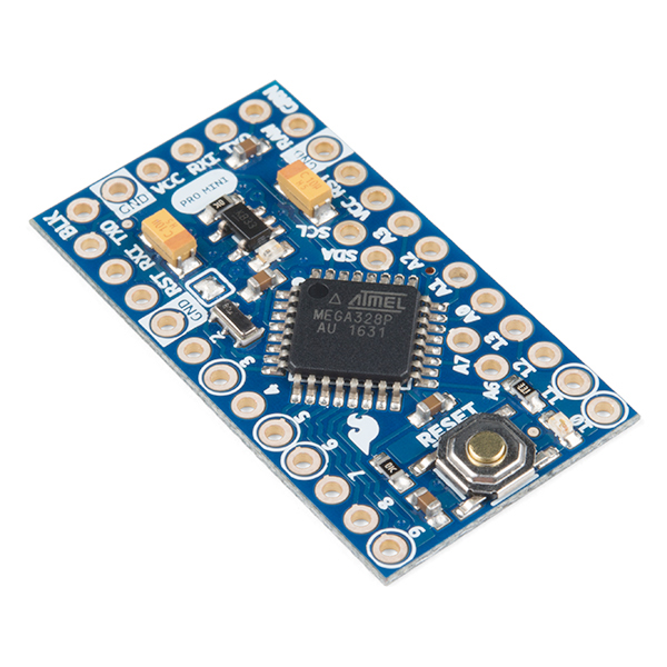
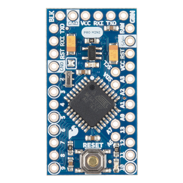
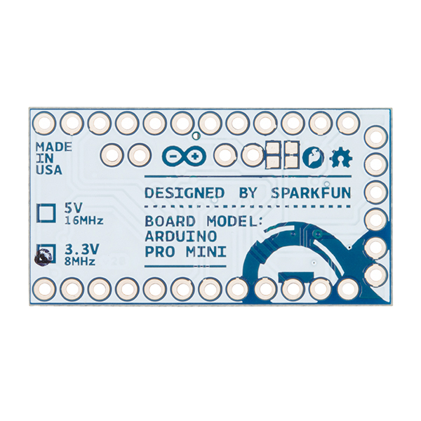
It's blue! It's thin! It's the Arduino Pro Mini! SparkFun's minimal design approach to Arduino. This is a 3.3V Arduino running the 8MHz bootloader. Arduino Pro Mini does not come with connectors populated so that you can solder in any connector or wire with any orientation you need. We recommend first time Arduino users start with the Uno R3. It's a great board that will get you up and running quickly. The Arduino Pro series is meant for users that understand the limitations of system voltage (3.3V), lack of connectors, and USB off board.
We really wanted to minimize the cost of an Arduino. In order to accomplish this we used all SMD components, made it two layer, etc. This board connects directly to the FTDI Basic Breakout board and supports auto-reset. The Arduino Pro Mini also works with the FTDI cable but the FTDI cable does not bring out the DTR pin so the auto-reset feature will not work. There is a voltage regulator on board so it can accept voltage up to 12VDC. If you're supplying unregulated power to the board, be sure to connect to the "RAW" pin on not VCC.
The latest and greatest version of this board breaks out the ADC6 and ADC7 pins as well as adds footprints for optional I2C pull-up resistors! We also took the opportunity to slap it with the OSHW logo.
Can't decide which Arduino is right for you? Arduino buying guide!
Note: A portion of this sale is given back to Arduino LLC to help fund continued development of new tools and new IDE features.
- ATmega328 running at 8MHz with external resonator (0.5% tolerance)
- Low-voltage board needs no interfacing circuitry to popular 3.3V devices and modules (GPS, accelerometers, sensors, etc)
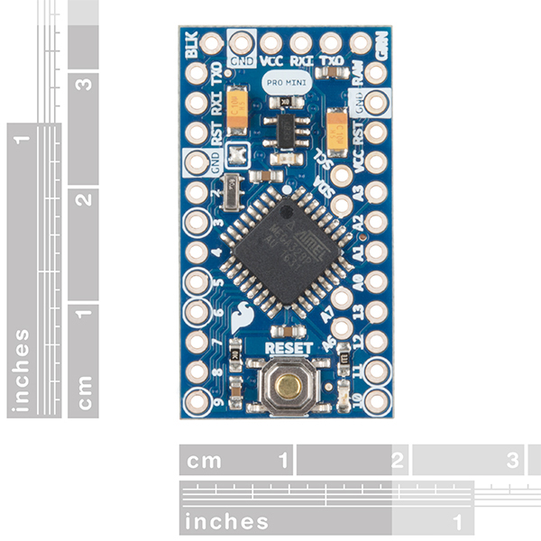
- 0.8mm Thin PCB
- USB connection off board
- Weighs less than 2 grams!
- Supports auto-reset
- 3.3V regulator
- Max 150mA output
- Over current protected
- DC input 3.3V up to 12V
- On board Power and Status LEDs
- Analog Pins: 8
- Digital I/Os: 14
- 0.7x1.3" (18x33mm)
Arduino Pro Mini 328 - 3.3V/8MHz Product Help and Resources
Das Blinken Top Hat
January 22, 2014
A top hat decked out with LED strips makes for a heck of a wedding gift.
MiniGen Hookup Guide
May 22, 2014
Using the MiniGen, SparkFun's Arduino Pro Mini signal generator shield
Interactive Hanging LED Array
April 10, 2014
Learn how we converted 72 lightbulbs into an interactive LED array for our conference room.
LED Cloud-Connected Cloud
February 22, 2016
Make an RGB colored cloud light! You can also control it from your phone, or hook up to the weather!
Choosing an Arduino for Your Project
December 11, 2017
Examining the diverse world of Arduino boards and understanding the differences between them before choosing one for a project.
Reducing Arduino Power Consumption
November 10, 2016
A tutorial about different ways to reduce the current draw for your next Arduino project the easy way.
Wake-on-Shake Hookup Guide
March 13, 2015
A basic hookup guide for getting started with the SparkFun Wake-on-Shake. The board gives you the ability to put your project into hibernation until bumped or shaken awake using the ADXL362 accelerometer. This means you can design projects meant to stay inert for long periods of time, possibly even several years, depending on the battery type used to power the project.
Motion Controlled Wearable LED Dance Harness
January 30, 2019
Control LEDs based on your movement using an accelerometer! Make your LEDs breathe by fading in and out when laying on the floor, turn off the LEDs when moving to your side, or make the LEDs blink in a headstand!
Single Supply Logic Level Converter Hookup Guide
August 9, 2018
The Single Supply Logic Converter allows you to bi-directionally translate signals from a 5V or 3.3V microcontroller without the need for a second power supply! The board provides an output for both 5V and 3.3V to power your sensors. It is equipped with a PTH resistor footprint for the option to adjust the voltage regulator on the low side of the TXB0104 for 2.5V or 1.8V devices.
Using the Arduino Pro Mini 3.3V
September 5, 2013
This tutorial is your guide to all things Arduino Pro Mini. It explains what it is, what it's not, and how to get started using it.
LiPo Fuel Gauge (MAX1704X) Hookup Guide
February 23, 2023
Monitor your LiPo battery with the LiPo fuel gauge! In this tutorial, we will be using the MAX17043 and MAX17048 to monitor a single cell, LiPo battery over the Arduino Serial Monitor. We will also connect a display to view the output without the need to connect the microcontroller to a computer.
Flashing the Bootloader
This should only be done as a last resort
Most likely your board isn't bricked, unless you have done something drastic like modified the fuses. In which case, reflashing the board probably won't help you.
However, if you have no options left and want to try to reflash the bootloader with an Uno or RedBoard. Here are links to some tutorial to get you started:
- https://learn.sparkfun.com/tutorials/installing-an-arduino-bootloader
- https://www.arduino.cc/en/Tutorial/ArduinoISP
- http://www.instructables.com/id/Burn-a-New-Bootloader-Arduino-Pro-Mini/
(*Make sure to upload the ISP sketch to the programming board. Also, tie the VCC pin to the 5V pin of the RedBoard or Uno. This will set the chip on the Pro Mini to 5V without having to worry about any logic level conversion. Lastly, be sure to double check the board options you are selecting so that the Arduino IDE uses the correct bootloader hex file.)
Core Skill: Soldering
This skill defines how difficult the soldering is on a particular product. It might be a couple simple solder joints, or require special reflow tools.
Skill Level: Rookie - The number of pins increases, and you will have to determine polarity of components and some of the components might be a bit trickier or close together. You might need solder wick or flux.
See all skill levels
Core Skill: Programming
If a board needs code or communicates somehow, you're going to need to know how to program or interface with it. The programming skill is all about communication and code.
Skill Level: Rookie - You will need a better fundamental understand of what code is, and how it works. You will be using beginner-level software and development tools like Arduino. You will be dealing directly with code, but numerous examples and libraries are available. Sensors or shields will communicate with serial or TTL.
See all skill levels
Core Skill: Electrical Prototyping
If it requires power, you need to know how much, what all the pins do, and how to hook it up. You may need to reference datasheets, schematics, and know the ins and outs of electronics.
Skill Level: Competent - You will be required to reference a datasheet or schematic to know how to use a component. Your knowledge of a datasheet will only require basic features like power requirements, pinouts, or communications type. Also, you may need a power supply that?s greater than 12V or more than 1A worth of current.
See all skill levels
Comments
Looking for answers to technical questions?
We welcome your comments and suggestions below. However, if you are looking for solutions to technical questions please see our Technical Assistance page.
Customer Reviews
4.6 out of 5
Based on 54 ratings:
2 of 2 found this helpful:
My favorite Arduino board (maybe)
With the possible exception of it's 5V sibling, this is my favorite Arduino board. It's small, it's inexpensive, and it does everything one would expect of an Arduino.
4 of 4 found this helpful:
The low voltage feature is awesome!
So removing the solder blob allows you to run the board off a 3.7V lipo. from full charge(4.2V) to discharge (~3.2V) the microcontroller runs its 8MHz quite happily with no complaints. Does really well in deep sleep modes as well.
1 of 1 found this helpful:
I want AREF:
The biggest problem with Sparkfun boards is, the AREF missing!!! So don't buy it if you want to scale the sensor readings or to improve the resolution of your measurement.
3 of 3 found this helpful:
Great little Arduino
This is perfect if you want to embed an Arduino into a small project. The 3.3v version is awesome as you can directly connect to things like the small WiFi and nRF24 radio boards that are native 3.3v chips - no need for the Sparkfun 5-3.3v converter board.
Make sure you pick up a FTDI 3.3v logic board or cable. The 5v one you probably have lying around won't do you any good with this board.
2 of 2 found this helpful:
Pro Mini
Really great product. Reasonable cost, documentation sufficient, and great compatibility with Arduino family. Low power consumption, too less than 10ma - that along with the small size and easy hook-up (flexible use of header pins if desired) makes this my go-to Arduino platform.
2 of 2 found this helpful:
Solid
I really like this and the 5V version. For many projects I prefer them to the UNO. My only beef and the reason for the loss of a star is the fact that pins A4 and A5 are not on the outside of the board and worse, they are offset. So for I2C you have to run wire or build your own board. Not the worst thing ever, but for a tiny bit bigger of a footprint, I personally would have preferred those pins on the outside.
3 of 4 found this helpful:
Good match for balloon project
Some of our local amateur radio folks (aka Hams) are supporting a climate change class taught at Williams College. Last year the class launched a balloon that reached 30K feet and we received telemetry data from the balloon. This year we plan to design a more capable payload for the balloon. The light weight, low cost, low power requirements, and availability of software make this product a great choice for generating telemetry data.
2 of 3 found this helpful:
Does the job but a 9V battery let the smoke out of the voltage regulator
I'm using this as an ADC to convert an analog pot into a digital value which is then input into a Raspberry Pi. I had a 9V battery in my project case, so I tried powering this board up using the 9V line on the RAW pin. The product description for this board says the max voltage on RAW is 12V (and the schematic says 16V), but as soon as I connected 9V to RAW, there was a loud "POP" and the bitter taste of disappointment (and melted plastic) in the air. Happily, it was only the regulator IC which blew, and I'm able to power and use the rest of the board using the 3.3V pin on the Raspberry Pi driving the Vcc line on the FTDI header.
Another great SparkFun product, but I still wonder what happened with the voltage regulator. Anyone had a similar experience?
Perfect size and Perfect price..
I built my wife a birthday card using this board and some red LEDs. The Pro Mini is the perfect size to hide in a piece of cardboard along with all the wiring and a coin battery. She loved the card.. I constantly look for opportunities to use one of these little guys.. Great product!
Reliable chip
This low-voltage arduino can fit every tiny, cableless proyect you can imagine!
The perfect Arduino board for highly miniturized projects
I'm currently hacking a PS2 remote controller, in order to use it to drive a RC DIY quadcopter. I emptied the controller, because I found the electronic inside very ugly, and wanted to make all the logic of the controller on my own. I like using Atmel microcontrolers, but I don't have the skills to solder CMS ones: indeed, any DIP-24 package don't fit in the controller. Then, the Pro Mini was the perfect board: it's tiny enough to fit in, and there's no need to CMS solder.
Almost amazing
I seem to be collecting microcontroller boards and these are my newest acquisition.
I've used one of these very successfully in a micro/macrophotography stacking rig.
I power mine with 12V or 9V to the RAW pin. No smoke. If there is smoke, something is wrong with your unit or wiring. I always use these with external reverse polarity protection diodes (Schottky) or even MOSFETs. It's easier than you might think to wire things up backwards.
I am a bit perplexed, however, by the location of those four analogue input pins. I guess it makes the board a bit shorter by putting them there, but I'd rather a board that's 5mm longer with those pins placed in-line with the others, two per side.
Another thing to note is that the silk-screening for the TX and RX pins is quite confusing unless you consult the ATMega328 pinout. Arduino UNO, for example, labels their pins TX
1 and RX
0. Letting you know that TX (out) is pin 1, and RX (in) is pin 0. On this board, however, the pin numbers are missing - but to a casual observer, it may not appear that way. Instead, the letters I (in) and O (out) appear, which are easy to confuse with pin numbers. RXI is in fact pin 0, and TXO is in fact pin 1. So beware of that, if you plan to actually use those for something other than serial.
Nice but quirky
I bought 3/3V and 5 V versions of this and got an immediate download and run. Then they stopped taking downloads and it took 2 days to figure out what it was. In my circuit I was using one of the BT boards (Bluetooth) hooked up to the RX and TX pins. With that connected it will not program. Pull one of the two lines and it programs fine. It's a little irritating but it works and the mini pro is the exact right size and does a great job. The only other thing I can say is that you can't easily hook A4 and A5 to your breadboard if you want to use I2C. You have to solder wires in to A4 and A5 and plug the rest into your breadboard then plug the wires from A4 and A5 into your breadboard. A little irritating but if they were outside then the board would be bigger and it would not fit what I need. Overall I am happy with the mini pros I bought.
Hi, You'll commonly want to disconnect any devices from your hardware serial when programming. The trick is to run software serial for your Bluetooth device. That will move the communication lines over to non hardware UART lines and will allow you to leave the BT hooked up when programming.
Love these things
I've basically abandoned all Arduino models except this and the Moteino (which is basically a Pro Mini with a radio). I haven't done a project that needed a larger processor or more IO, and for $10, you can make a lot of really cool stuff!
Nice solution
This is a great way to get an MCU into a tiny project based on the easy-to-use Arduino platform. It's very powerful and has the same numnber of i/o pads as the big boards. Getting the program on is a bit tricky, but not too terrible once you have the right set-up.
Really useful in prototyping
I really like it. It is the best Arduino board for the small size projects. I recommend this product.
0 of 2 found this helpful:
I didn't realize it has only one UART port.
I was spending a lot of time trying to figure out why I couldn't get the Serial1 port to work as it kept screwing up and hanging the Serial data also. I finally looked at the specs and noticed that it has only one UART which is the same as the FTDI port. Actually it doesn't make sense to me. Why would there be wasted RX and TX when they are the same as the RX and TX on the FTDI?
Great very little Arduino
The Pro Mini either in 3V or 5V is my goto Arduino when I don't need the traditional form factor for shields. They are just the thing for building into zombie costumes or tiny robots. These Sparkfun Pro Minis and well made and well supported.
Excellent low power board
I still could not believe the low current it takes in power down mode. (I hope I use the board correctly to measure the ultra low power down mode current) It is ~200 nA with out the power LED. I have seen others do many changes to the board to get 4.5uA, but just removing only the LED I was able to get it down to ~200NA. It is probably due to MIC5205 Vreg the board. Great Product, love it.
Love this form factor
Yes, there's some additional educational overhead because it has less onboard, so this shouldn't be your first arduino. But! It's tiny and uses less power (good for batteries), and fits into wee little projects. This is my go-to device for my embedded systems projects, though I tend toward the simple, so I'm not driving huge light arrays or anything requiring a lot of computational horsepower. I mostly do small art projects or simple detectors. For those, this thing is way more than enough functionality.
Homebrew drone made easy
This is the perfect little device, great for miniaturizing your projects. It did take me a while to figure out how to program (if programming with an Uno, for instance, you have to remove the ATmega).
Excellent little power house
Easy to get up and running with these guys, sufficient memory, compatible with a ton of 3.3V devices without the need for level shifting...same reasons everyone else loves them...and they aren't expensive at all...
Amazing capability at an incredible price point and small footprint
The Pro Mini is a powerful tool in an incredibly small footprint. It took me a bit to get going with it but there really are no great mysteries to solve. Just carefully follow the "Getting Started Tutorial" and you'll be fine, even if you're a newbie like me. For the price this little device can't be beat!
Small, tiny and sips power
The Arduino Pro Mini is a very powerful Arduino with lots of features and I/O in a very small package. If you need an Arduino that is physically small or has to run on batteries/low power this is a great choice. This comes in a 5v and 3.3v version, as well as an 8 or 16 MHz option.
One typical usage might be a remote sensor that needs to report data (say temperature or weight) occasionally. The Pro Mini may wake occasionally from h/w powerdown, power up a radio, report the data and then powerdown again. Depending on the factors you might be able to run a year or more on AA batteries.
The Pro Mini comes without headers (you need to add your own) and without a USB connector, so to program it you will need Sparkfun's serial adapter for that. Although it's small it does come with a voltage regulator that can feed peripherals as well as a handy reset button.
Note for ultra low power applications there are many tricks you can find online such as removing the power LED as well as the voltage regulator (assuming you don't need these). Removing one or both of these can have substantial impact on battery life.
Overall it's a great Arduino in a tiny package!
Tiny and power efficient
If you need to reduce the size or power of your project, graduate from the Arduino Pro to this board. Possible to power the MCU directly bypassing the on-board regulator if low power is the goal. I wish the LED wasn't on an SPI pin, but that's the same with the larger board too.
Versatile and Easy to Use Device
Perfect for my various embedded projects, and at amazingly low cost.
i find that the "Sketch" programming approach used by the Arduino folks is great for most applications, but that the ability to embed lower-level code in the applications is also helpful for specialized applications, and, if necessary, to reduce application footprint and save flash space.
The flash capacity of this device (32 KB) is pretty good and having purchased a few of these from Sparkfun, the quality is excellent. I have never received a DOA device.
My current project is using this device and Sparkfun's microSD level-shifting breakout to add an insane amount of storage (like 64GB) to an early 1980s industrial control Z80-based system that has just 16K RAM on board. Weird but fun. I have the hardware working and am developing the communication protocol and device driver routines.
I have also used this device with environmental sensors in a musical training application, where the device and sensors are embedded -within- a medieval instrument to provide wireless, real time feedback to the musician to help him/her improve their playing. Another "weird but fun" thing.
Great little computer
Versatile, I have used both the 3.3V and 5V versions for projects ranging from replacing a Dan Foss fan controller in diesel motorhomes to solar control to smart on/off switch functions in motorhomes.
Easy to program and very reliable, and cheap, what more could anyone ask?
Mini and mighty
Using it to miniaturize an Uno/ESP8266 design. Great partnership!
It is very aprpopiate for our project
We apply it in academic experiment with Smart Sensors.
I'll give these a "5". With 4 smallish projects planned, these were "on sale" so I snatched up 5 (but two were the 5 volt version). Been using these for a few years, and they work better for my projects than an official size Arduino.
Easy to use
Minimal soldering easy programming multitude of great library's.
Amazing product!
I use it for almost my project, I cannot imagine how I could do all I do without it. Its key-feature is the size. You can put it almost everywhere.
What is in my dreams? To have the Pro Mini with a larger built-in RAM. Sometimes 32K of flash memory can be a limit.
Perfect for my sensor project
This is a great, affordable breakout board for my home automation and sensor project. It's very easy to breadboard or place into a PCB of my own making or even stripboarding. It's very easy to program and has more power than I need, I particularly like the lower voltage requirements over the 5.0 volt board. The fact that I bought them on sale for half price makes them particularly attractive.
Great board, make sure you get FTDI to upload code
I recently used the Arduino Pro Mini in a prototype because I needed the full power of the Arduino, but in a smaller form. The Mini has been great and did everything I needed. Specifically, I needed to use 10 digital pins and 1 analog pin.
I highly recommend reading the awesome tutorial in the documents section. This was my first time using the board and I ran into the following gotchas.
- To upload code, you need the FTDI Basic Breakout Board. See the tutorial in the documents section. It details how to upload code. You don't need the FTDI board once your code is uploaded (this saves on space).
- The digital D0 and D1 pins connect with the FTDI header's TXO and RXI pins. Because of this, they do wierd things when your board is connected to your computer via the FTDI breakout board. When you aren't connected to a computer, they work normally. I did some testing while connected to the computer, so I decided to use different digital pins (I had extra digital pins I wasn't using).
- It doesn't supply pins that give power for your components. Since I only needed 3.3v at a low amperage, I turned on an extra digital pin to supply power. If you need different voltages or more amps however, you'll need to add some external power to your components.
Thanks again to Sparkfun for this great component and tutorials!
For when you just need the ATMega328P & Arduino bootloader
The ATMega328P chip, crystal and bypass caps on an easy to use board. Already programmed with the Arduino bootloader.
A decent board
Only one issue: I would put A4 & A5 on the edge and put A2 & A3 in the middle, because I2C is very popular, and the middle thing makes it awkward to use.
Otherwise, this is one of the best boards to use for low power - the leds and regulator are easy to remove, so the board draws the same current as a naked 328p. Perhaps I would also like to be able to solder a crystal to the board, rather than always use the internal 8 mhz oscillator.
I have built about a dozen projects with this board.
Excellent product and fast shipping to europe .
Great support
The support provided is amazing and enabled me to get up and running in minimal time.
Good boards
Just wish they would re-do two things: OK, you had to stick A4, 5, 6, 7 in the middle: we're grateful to have them! But why stagger them off the .1" grid? Couldn't you put them on the .1" grid with the other pins so you can still pin them down in a .1" perf-board? Surely you could shuffle other components around by the .050" needed to keep them aligned. And please bring back the .062" thick PCB instead of the too-flimsy .032" boards used now. The old .062" thick ones were rigid enough to be sturdy when prying them back up out of a breadboard without deforming but when you try to pull the current Pro-Minis back out of a standard breadboard they flex badly, and that can't be good for the traces and solder pads. What do you gain by the thin boards? Other than that, (and please just view this as a constructive criticism) they are great, really handy when you need to throw a little smarts into a sensor or actuator project.
Still my "go to" platform
Yes it's "old". Yes, it's "limited".
So am I.
And this little beauty does what it says on the tin, is easy to use, never lets me down, and is inexpensive.
Yes, I have to use "bigger" Arduinos for some things. I have webservers running in the Dev Thing and a similar Huzzah. And smaller things are fun sometimes, too... I have the little Sparkfuns and some "Trinkets".
But for day to day things... I use this, or in some legacy situtions, the ModernDevice RBBB.
And if I need 3v3, there's the 3v3 version of this.
Great product - be sure to handle the magic smoke issue!
Just like @Member #162075 I too faced the dreaded magic smoke issue with a 9v - but in my case, it was working fine, until it wasn't. I'm pretty sure I must have accidentally reversed polarity though! It is so easy to accidentally do that, and a mere touch is all it takes the fry the puppy. And it is only the voltage regulator - the rest of the board is fine when connected via VCC from the FTDI header. Also, I disconnected the wires as soon as I saw a little whiff of smoke, but the damage was done. Connecting anything to RAW at that point just exacerbated the problem and caused a slow but sure death.
Just make sure to handle reverse polarity in the circuit connecting to RAW and GND. Even a simple diode (I used the IN4001) protecting the polarity, while not the best solution (you have to account for the voltage drop of about 0.5-0.7v across the diode), it is still infinitely better than directly hooking up the input source to RAW and GND. After that approach, a second Arduino Pro Mini is chugging along fine with the 9v battery, and you don't have to worry about accidentally touching the wrong 9v battery leads to the connector and shorting the whole thing!
In all, a great little board for making a permanent/semipermanent board that is cost effective and small.
Nice affordable miniture Arduino but lacking Serial RX and AREF
I'm using this in a solar charger project I have and wanted to share my suggestions.
1) I cannot get the Serial RX to work or receive anything from Serial Monitor. I have confirmed with both a logic analyzer and oscilloscope that the RXI pin is being driven with proper 3.3V UART and the bytes and settings are correct. I can transmit (println()) just fine and see the output on the Serial Monitor. Not having serial RX is limiting my project to not being able to run a calibration routine (receive measurements from host and calibrate). I don't think it's possible that I damaged the RXI pin, because I can download code just fine. Serial.available is never > 0 no matter what I send, meaning that it never receives any serial, but testing shows it does have the proper signals.
2) There is no AREF pinout, this would be nice to have and essential. It's especially useful for my application where it would be safer to have a stable Analog reference to not accidentally misread the battery and solar voltages and create a charging safety issue (overdrive the battery, throw off MPPT algorithm and create instability, ...).
Overall it's a cool board and nice form factor!
Great board for hacking
I love these boards, getting the 8mhz version is an easy way to start a low power project!
Excellent value
I needed an inexpensive and physically small 3.3V processor for my project and this Pro Mini fit the bill.beautifully. Having the on-board regulator allows the system to be powered from a 12V source which was needed elsewhere in the system was also an advantage. However, because my system is battery-powered I did need to eventually disable the regulator and provide an external source of 3.3V. Fortunately the board provides an easy means to disable the power-hungry regulator.
small and perfect!
is there anything better than this tiny, easy to use computer?
Works like it should
Works exactly like it should so 5 stars.
Great board, great price
these are awesome little development boards. Highly recommend the FTDI breakout programmer, makes life very easy. This board is very thin, compact, and has plenty of IO options. Easy to solder.
It's from Sparkfun
Of course it's awesome, it's from Sparkfun.
Pro Mini 328
Useful as low-cost and already-wired processor in testing data communication (RS232) programming with a PC serial port by assembly-language and by the Arduino IDE
Great for such a tiny thing
If you need to integrate a small ready-to-use arduino/ATmega in your project this is a pretty great little board. this is made to be as small as portable as possible. Even the PCB itself is thinner then usual.
Wonderful little board for projects!
I've been using the Pro Mini boards since they were first introduced and they're just the ticket if you need a super small Arduino board for your project. I like to keep a few of both 3.3V and 5V versions on my bench as they're my go to board for quickly prototyping circuits.
I have a project that currently runs on two AA alkaline batteries (3.0-3.1V). Is that enough voltage to power this 3.3V Arduino?
Hi there, it sounds like you are looking for technical assistance. Please use the link in the banner above, to get started with posting a topic in our forums. Our technical support team will do their best to assist you.
That being said, the graphical datasheet specifies a minimum recommended voltage of 4V. Otherwise, you will need to dig into the schematic for the voltage regulator, reference its datasheet, the AtMega328 datasheet, and the firmware fuse settings... or just try it out yourself.
https://hackaday.com/2020/04/06/subwoofer-gets-arduino-brain-transplant/
Nice work! Thanks for posting link!
I wanted to try to work directly with the posted Eagle schematic and layout. But when I downloaded them, there were libraries that they reference that seem to be missing, and are not in the regular set of Sparkfun libraries that I already have long since downloaded from GitHub. I am wondering if they are older out-of-date libraries? The two libraries are called "Sparkfun.lbr" and "Testing.lbr". Does anyone know where I might find these Eagle libraries?
Thanks in advance to anyone who might be able to help! :)
I am using one of these in a project to control one of the RN-52 Bluetooth audio modules (sparkfun breakout). The project has it’s own 3.3v power supply for the Arduino and the RN-52, which leads me to my question:
Is it safe for me to allow the project power supply 3.3v regulator to provide 3.3v to VCC with a 3.3v SparkFun FTDI Basic Breakout hooked up to the programming header? I noticed the first time I hooked up the FTDI with the power supply off that it fed 3.3v through and lit up the “on” LED on the project power supply.
I considered placing a diode on the VCC connection that feeds the Arduino when on project power, but at 3.3v I really don’t want the forward voltage drop, and I have worries about overpowering something like a 1N6263 schottky diode.
You should only have one power supply on the VCC/3.3V line at any given time. I would see about cutting the trace on the back of the FTDI. There is a solder jumper that that lets you select 3.3V or 5V. It is basically 3 pads with VCC in the center and 3.3V on one side and 5V on the other. Usually you connect one of the sides to the center. If you just isolate the center though you should end up with no power on VCC.
Note: I haven't checked the schematic to double check this will work so proceed with some caution.
Thank you for confirming what I suspected!
I looked at the schematic for the FTDI, and it looks like clipping that trace would leave the FTDI's VCCIO pin floating, which I imagine would cause some problems.
I think what I will need to do instead is just desolder/clip the power pin of the header (JP1, Pin 3). This will leave the FTDI unable to power other projects, but that is ok.
Thanks for your help!
Don't forget if the Arduino is powered, the VCC line will end up powering the FTDI which should power VCCIO. It might act weird between the time you plug it in to your computer and the time you power the Arduino though.
good point, Thanks
A thought that might help some others if they run into the same situation as I did on this board. This board lacks the 1K resistors on the RX and TX lines. This seems to cause some programming issues when something else is attached to the broken out RX and TX lines. I noticed that programming was hit or miss without them, and for now, it seems that adding in the 1K resistors on the RX and TX lines between the board and the secondary UART device helps greatly. Anyone else had that issue? Those resistors are pretty standard in most of the other "Arduino" designs.
I got Arduino Pro Mini 328 3.3V/8MHz with S20G label on voltage regulator. I can't find any datasheet or vendor, but I measured that it consumes 1.6mA in sleep with power LED on (and 230uA with LED removed) and less than 7mA awake. Surprisingly good result. I would just like to know maximum current rating and quiescent current.
It's the MIC5205. This datasheet link should work for a few days :)
Is a 3.3V FTDI Basic required, or will a 5V connection safely drive the 3.3V Mini over the programming headers without risking damage to the board or any 3.3V devices connected to its I/O?
The power pin on the FTDI connection is VCC and not RAW so it will not go through the voltage regulator. 5V is safe for the Pro Mini, but you will also have 5V on anything connected to VCC (possibly including 3.3V sensors). This will also cause the Pro Mini to operate at 5V meaning its I/O will also be running at 5V. Whether that will risk damaging another board depends on the specs of the sensor.
Any chance of getting the board into the Sparkfun Library with the off-grid headers? I'm designing a PCB to mate with the arduino and it would be nice to have those available from the get-go.
agreed! Would be nice to have in the Sparkfun Library.
If anyone is interested I made an updated footprint to put in my library that includes all holes. It has NOT yet been tested as I'm waiting on the PCBs but the dimensions are taken directly from the eagle file given on this page.
Hi, I am looking for something similar. I am looking for a part which might consist of correctly spaced out female headers, to mate with the Arduino Pro Mini. If you could give me a link, that would be awesome.
Can I upload to the 3.3v mini using an uno R3 board? Would this work - take out the ATmega328 chip on the uno and connect BLK, GND, VCC, RXI, TXO, GRN (on Mini) to Ground, Ground, 3.3V, RX, TX, reset (on the uno) and then upload a sketch selecting the 3.3v mini board from tools in the Arduino IDE?
I meant to say when you plug in all those things respectively. Anyway, I tried it with the blink sketch and it seems to work.
What did you select as the board / processor in the Arduino Dev Env?
I found out from an Instructable and from trying it that you pick the board you're trying to program, not the board (i.e., UNO) that you are programming with. Just FYI for anyone reading this.
Has anyone ever used an Arduino Pro Mini as a SMD on another board? Any advice?
My mistake ... didn't account for it being 8mhz instead of 16 mhz as I usually use!
Could one hook up one of SF's small lipo batteries directly to this? Or would something else be needed or recommended?
Thanks
A bit late, but for the record, I run mine this way. LiPo to RAW (I've even done VCC) works fine.
Can I run this "Arduino Pro Mini 328 - 3.3V/8MHz" with CR2032 coin cell battery ? Since nominal voltage of this battery is 3v , and this will be reduced with time , this arduino pro mini will work till which minimum voltage ?
I just got one of these to work with a 3.3v interface chip. However, I cannot get it to program with any of the USB-TTL breakouts I have. i don't have FTDI - only the PL2303HX-based versions. I can do loopbacks on these boards but they will not program the pro mini. Is there something else that I have to do when using one of these alternatives? They don't bring the DTR out - just RX, TX, GND, and VCC (which I don't connect because it's powered off the breadboard).
The DTR pin on the FTDI boards is used to do a reset of the board to put it into bootloader mode. If you don't have DTR broken out you will need to manually reset the board. Basically when the code is finished compiling and you see the white text giving you the file size etc., hit the reset button and it should work.
Tried that a few times, but maybe didn't hit the right time slot. I WAS able to use an UNO board with the processor removed, jumpered over to it. Just picked Pro Mini with the correct processor and speed and it worked first time! At least I know it's not a bad board!
In the description of this product, it says that the ADC6 and ADC7 pins are broken out. Does the Arduino software natively support A6 and A7?
Yes. The Pro Mini is actually an official Arduino board so everything is fully supported in the IDE. I believe this is the only official Arduino board to use these pins and the ATMega328 PTH version does not have them, so very old versions of the IDE might not support these pins, but any IDE from the past 3 years (since this board was released) definitely will.
Just to clarify: If we connect the 3.3 Pro Mini to the FTDI Basic Breakout via the broken out pins, it will fry the board? ie) USB is 5V and the ProMini is 3.3V?
So we would want to leave VCC disconnected from the broken out pins and instead connect the FTDI power to RAW on the Pro Mini?
If you use a 5V FTDI it will put 5V on the VCC line. If you use a 3.3V FTDI than 3.3V will be on the VCC line. I believe the maximum voltage the ATMega328 can handle is 6V (absolute max, not recommended) so the IC is fine. Basically the 3.3V designation of the board is the value of the voltage regulator and when the board is powered through the regulator the I/O voltage of the controller. In other words if you put 5V on VCC than you will just have a Pro Mini running at 5V. As long as you don't have components that will fry at 5V connected to the board everything should be fine.
I like the 5v version of this enough that I wrote KiCad .lib and .mod files for those who want to put an Arduino Pro Mini on a PCB of their own design.
Free.. Should work just as well with 3v3 version?
http://kicadhowto.org/LibLib.htm
The small size of the Arduino Pro Mini reduces the expense of the PBB you are making, as there is little board area under the Arduino.
Hello, If I want to connect a 1 cell Lipo Battery (3,7->4v) can I connect it directly to VCC or do I have to use the RAW pin ? Thanks.
The ATMega328 typically runs at 5V and its rated maximum is about 6V, so you should be able to put anything up to 6V on the VCC pin. The RAW pin will run the voltage through a 3.3V regulator meaning that VCC will now be 3.3V. Either of these will work, one may be preferable over the other based on the peripherals you are using and their voltage requirements.
I originally bought this for my project because of the cost. I found the location of the I2C SDA & SCL pins (A4 & A5) to be so annoying that I just bought a Pro Micro https://www.sparkfun.com/products/12587 instead. I am much happier with it and I don't have to worry about keeping up with [the now rare] USB Mini cable for my FTDI Basic.
I find it pretty ridiculous that this thing has 2 on-grid GND pins and 2 on-grid RST pins, yet the I2C is off-grid. Could have been a nice little board otherwise.
The off-grid decision is actually very intentional. Enough people solder headers to the board and stick them in a breadboard that we didn't want to run the risk of you shorting those pins to something else. The original was based off of the Arduino Mini and uses the same footprint, I believe the I2C was actually added later on. In general its a great little board, but so is the Pro micro. Thanks for the feedback.
Oh, by off-grid, I meant "not on the edge with the other pins." I agree that if you are going to put pins internal to the board, they shouldn't be in line with the edge pins. Otherwise a beginner like me would make that mistake.
However, this is a compromise that I think you should consider
How would this best be connected to a raspberry pi? i2c, SPI, UART of some sort?
i do not want to apply a full FTDI and USB connection between the two.
So...I was told if I had an LED set up requiring 12V, and an XBee that I was controlling off this version of the pro-mini, I would need a step down regulator in order to only use one power source for all three things. Is this not correct since it has an on-board voltage regulator? Couldn't I hook the 12V battery to the pro-mini's raw pin, hook the LEDs directly to the battery, and the XBee to the VCC? I'm still learning all this electronics stuff so I want to be sure I don't fry my Arduino.
The Arduino buying guide suggests that this has: 14 Digital I/O 6 Analog 6 PWM 1 UART
Here it says 8 analog and no mention of PWM.
Here is what I want to know: Does this thing offer PWM? On what pins? Are the analog pins pulling double duty?
The ATMega328 has 14 digital I/Os, 6 of which do PWM, and 2 of which are the UART port. It also has 6/8 analog pins. The original Arduinos use DIP chips and those have 6 analog pins which were all broken out. The SMD chips have the 2 extra pins which were never really broken out partly because no one wanted to change the footprint. We did add those extra two pins on the current version of the Pro Mini. Otherwise it has the exact same pins as any other ATMega328 based Arduino including PWM. If you take a close look at the picture of the Pro Mini you will see an extra ring around pins 3,5,6,9,10, and 11, these are the PWM pins.
Hard as I look, I can't find that "power isolation jumper" that's on the schematic, nor the footprints for the I2C resistors (I just see the I2C pins broken out to the off-grid headers.) Am I missing something here?
The "power isolation jumper" is bridged - it's the blob of solder by GND and RST.
The two resistors are optional, and you can find the footprints on the bottom of the board by the A4 and A5 off-grid pads.
Ah, I see the resistor pads, and the jumper in the pictures above. However, my board is different -- there is no space between the crystal and the 10uF cap on mine! Out of 6 Pro Minis that I have, 2 of them have the jumper and 4 don't (but all have the resistor pads). I guess the jumper was added after the resistor pads.
Yep - looks like the resistors were added in v1.3, while the solder jumper was added in v1.4. As the 'previous versions' list only points to a product matching the v1.2 iteration: should you need the schematics/board for v1.3, just change the 'v14' in the links to 'v13' :)
Aha, thanks. I'd never seen the "previous versions" link before... :-)
So the question then becomes: will the voltage regulator get unhappy if I connect my board to the FTDI breakout and "back-power" it with 5V? I looked at the datasheet but couldn't find any info about what happen if Vout is higher than Vin.
Can I use this just to drive things? Like interchangeable tools sort of.
Could I use this just to drive a servo motor?
Does this support I2C? I'm not really familiar with I2C yet, but I want to learn and I am wondering if I can use this with an accelerometer to build a self-balancing robot. I've got a few months experience with an UNO, so don't spare me the technical details.
Yes, A4 and A5 are the I2C lines or the Arduino. Basically the Pro Mini is the same circuit as the Uno just a lot smaller and without a USB port, bu the actual microcontroller is the same, so anything the Uno can do the Pro Mini can do. This Pro Mini also only runs at 3.3V/8MHz.
Cool thanks!
Are the rx/tx lines 5V tolerant? I want to know if it is possible to program this with a 5V FTDI board, without needing to get an additional 3.3V FTDI just for this board.
Yes, the only difference in the 3.3V and 5V Pro Minis is the crystal and the voltage regulator. Since the FTDI bypasses the regulator the only difference is the speed the run at. The ATMega328 is fine at 5V. Keep in mind if you have 3.3V on VCC and 5V on the I/O pins that is technically out of spec (you shouldn't put more than VCC on the I/O pins), but will probably work as well. Keep in mind that the 5V FTDI will put 5V on the VCC line, so make sure you don't have any 3.3V only devices connected when you do this.
Does the VCC pin output 3v3 when I put 12V to RAW pin ?
[self-answer : yes it does.]
Has there been any talk of an Arduino Mega like this? A megamicro? I love the pro mini but my project uses a relay shield and an sd shield and a few buttons and switches so now I am out of pins for a LCD. 1st world problems.
We do have a version of it here but because of the number of pins, the layout is a bit bigger.
Oh! I saw that and it didn't click in my tiny duke head. Layout size isn't a problem, I just ran out of pins. Thanks!
Hello! I it possible to run 3.3V version with 1.8V on 1MHz ?
I was thinking: what if a board like the Pro Mini had a pinout that was compatible with one of the four headers of the Arduino shield form factor? For instance if one side of the board had digital I/O 8-13, GND, AREF, and SDA/SCL, in that order? Then if you were building a project around a standard Arduino shield (but didn't want to use a standard Arduino) you could put a socket header on those 10 pins and plug the Arduino right into one corner of the shield (or just solder it to the shield, pin-to-pin), and then wire up the remaining pins by hand, or something...
Something like that could be nice as a way to make Arduino projects more compact, while still using the same shield design.
I'm having trouble with floating inputs. No matter what I do I can't get the analog inputs to stop floating. I've tried pull up/down resistors, that just resulted in 0 or 3.3v readings. I have 2 of these and they are both doing the same thing. I've tried battery, USB, and regulated wall worth power.
This is the sort of thing you see if nothing is connected to an input. What are you connecting, and is the connection solid?
I am wanting to use this to drive 14 LEDs. If I use an external 3.3v supply (COM-00526) could I do this? I know in the Arduino website it says max 40ma per I/O, this is fine, but I need to supply about 300ma in total. If i use the external supply connected to VCC would I fry the chip by pulling 20ma through 14 of the I/O pins? This is going inside an r/c car so I would prefer to not have an external transistor board. Also, all 14 LEDs need separate control.
Thanks for the reply! I'm very much a noob with these, and the part about the shift registers has gone right over my head…. Is there a way you could explain that a little more? My plan is to have the Arduino turn LEDs on/off based on the signals it gets from the cars RX. I guess I'm failing to see how this works with the shift registers? The applications I am seeing with them is to turn a bank of lights on/off or cause them to blink. Not to have individual control of each LED.
Also, looking at the ATmega328 data sheet I'm failing to see anything other than the already stated limit of 150ma. Perhaps this is my ignorance showing through..
The getting started tutorial link is broken.
It should be fixed now!
figured out my own problem.. it was that I used a cheap china made PCB.. i guess for me to make a real prototype i will have to spend some more money :(
Why exactly is this running at 8MHz instead of 16MHz? I would like to use this at 3.3V but want the extra speed. Is it because you're worried about turning on too much I/O and dropping voltage too fast and throwing errors? I'm using this as a prototype, and am planning on building my own board, but wondering why you went with a 8MHz resonator. Thanks!
This is a limitation of the processor itself. If you read the very large datasheet for the ATmega 328, you'll find an interesting graph in the back that shows the maximum safe clock speeds for various VCC voltages. At 5V, you can reliably run it at up to 20MHz. But at 3.3V, you can only reliably run it at up to ~10MHz. This is why we use different resonators for the different voltages. (And note that the slower you run a chip, the less power it uses, which is better for battery-powered circuits. You can even clock these chips down to 32KHz, which runs programs very very slowly, but uses miniscule amounts of power).
It's not as bad as that I think, you should be able to get 12MHz comfortably.
Section 29.3 ("Speed Grades") of the ATmel datasheet "Atmel 8-bit Microcontroller with 4/8/16/32KBytes In-System Programmable Flash" states that the Maximum Frequency is linear across 2 intervals: between (1.8v=4MHz, 2.7v=10MHz) and between (2.7v=10MHz, 4.5v=20MHz).
This means that 3.3v implies a Maximum Frequency of 13.33MHz.
So I don't see why we are not running at (say) 12MHz instead of 16MHz - apart from one having to do a relatively-straightforward patch to the NewSoftSerial library, as detailed here: http://wiblocks.luciani.org/docs/app-notes/software-serial.html. I run at 3.3v and 12MHz, using optiboot recompiled for that speed as the bootloader and everything works very well.
Food for thought if you are looking for a new version? I know intrinsic support in Arduino IDE is a little smoother for 8MHz but getting 50% more cycles is not to be sniffed at.
I've seen it stated a bunch of places that using the wire library for Arduino enables internal pull-ups to 5V, and that you therefore shouldn't use it with 3.3V components. See, e.g.: http://playground.arduino.cc/Main/I2CBi-directionalLevelShifter and http://macdonaldm.blogspot.com/
But if I'm using a 3.3V arduino pro mini, I would imagine that the internal pull ups would connect to 3.3V, and this should be a problem. I can't find specifics about this anywhere though. Is this correct?
Correct - the internal pull-ups just pull the pin up to whatever is on the ATmega328's power input line. If it pulled them up to 5V, that'd be quite interesting as it would mean it would have an internal boost circuit ;)
I'm not OPPOSED to buying an FTDI breakout board, but I am trying to figure out whether I can program this puppy with the usbtinyisp I already have.
I'm able to use the usbtinyisp it to program my UNOs and Duemilanoves, but they both have headers that are clearly marked ICSP. This doesn't, but I am hoping that I can rig up a simple cable or jumper set. I'm sure the schematics would tell me, but I'm not sure what I am looking for.
Thoughts Anyone?
Check the schematic for the SPI pins. You'll need to connect to those and will require some jumper wires, but you should be able to.
Thanks. Sounds like a relatively trivial problem to solve, so these boards will be ideal.
According to the schematic, there is an LED on pin 17. Yet in the example blinky, it uses pin 13, and yes the LED blinks. So is there a mapping or translation, or is the interpretation of 13 different/unclear/wrong/strange ?
The interpretation of 13 is different/unclear/strange. Welcome to Arduino :)
What is referred to on the Arduino as 'Pin 13' actually maps to 'Port B, Pin 5' on the AVR, regardless of the chip's pinout which can vary. For example, in the DIL/DIP version of the ATmega328 you can see that it maps to physical pin 19. On the TQFP version of the ATmega328, however, it maps to pin 17, which his what the schematic is referring to. ( And to yet another, pin 15, on the 28-pin MLF/QFN package. )
Thanks very much for the response. I surmised there was a mapping, what I couldnt find and what you kindly provided was the TQFP diagram detailing it. Much appreciated.
With the different USB hardware on this board, I am wondering if it can use the Keyboard library like the Leonardo? It'd be perfect as a low power - low volt, low clockrate - board for an IR detector.
I was looking at the schematic and wondering, why do we need both C3 and C10? Would C3 or C10 work? can anyone explain that to me?
The larger cap takes a bit of time to let go of its electrons, the lower value cap lets them go more quickly. More precisely: the capacitors have different resistance and inductance, the 0.1 uF is used to smooth out high frequency ripples, the 10 uF handles lower frequency ripples. On board layouts you will find the 0.1 very close to the IC that is causing the ripples, the 10uF is more likely close to the incoming power.
C3 and C10 are both 0.1uF. C13 is the 10uF cap. However, I think I can apply what you explained to C3. It is there to smooth out the high frequency ripples caused by the ATMEGA and would be positioned physically close to that IC. Is that correct? If you were designing a circuit would you typically use one of these capacitors per IC?
So maybe I need some help, for someone with a bigger brain or more experience with these. I've built a clock using both a Arduino Pro Mini 328 5v/16 MHz & Arduino Pro Mini 328 3.3v/8MHz. I'm using the "Time Library" on the 328 5v/16 it is very consistent, I loos about 10 seconds a day and can compensate for this in code or eventually at a RTC. I bought 328 3.3v/8 thinking less power needed, lower speed, more energy efficient. This will eventually be a watch. I just hooked up the 328 3.3v Within 15 minutes it has lost 7 minutes. I'm running the same code on both processors. What did I miss? Please help if you know what is going on.
Self Edit - Helps to select the right board from the tools menu or you take 2 seconds to move the internal time clock 1 second froward. Divide by 2 - Kicks self and moves on - Doh!
it weighs 1,53g no-headers and with 3.67g with headers
i got one of these today, very nice. ya know if you reverse the raw and gnd pads you wouldnt have to solder the jst connector on the bottom of the board upside down :)
also you can program these using an UNO if you dont have an FTDi like me..
Does the RX/tx operate at 3.3v? I.E. I wouldn't need a logic level to connect to something like a raspberry pi.
http://blog.oscarliang.net/raspberry-pi-and-arduino-connected-serial-gpio/
Yes, if you power the board through the RAW pin it goes through a 3.3V regulator and so the board runs at 3.3V with 3.3V I/Os. If you power the board through a VCC pin though the board will run at whatever you put into that pin, so be careful not to put 5V on that pin.
If I put 5v in RAW, the TX/RX lines aren't voltage regulated? I want to avoid buying more boards (ie logic levels) or having a separate 3v battery source.
If you put 5V on the RAW pin the entire board runs on the regulated voltage. The ATMega328 is running at 3.3V, so all its I/Os (including TX/RX) run at 3.3V. The only place you will see 5V is on the RAW pin.
I'm not sure what I'm doing wrong. (n00b warning).
I've got the following project working with my uno (http://blog.makezine.com/projects/make-34/the-dryer-messenger/) but when connecting the wall wart dc jack to the pro mini I keep blowing it up. I connect the positive from the jack to "raw", then the negative to the ground on the mini board. I get a red light on the pro mini blinking fast and also the wall wart has a red light that begins to blink.
I'm not sure what I"m doing wrong. but the board powers up fine with a FTDI friend.
Thoughts?
wild guess, is the wall wart unfiltered dc? a single diode turns the power output off 60 times a second. if your volt meter reads less dc than the wall wart label and or your volt meter displays a significant voltage on the ac scale, that maybe the problem. try a capacitor on the wall wart output.
i am totally new to arduino, i need to connect a rf receiver and a transmitter to one of this boards, in the tutorial i got they use a duemilanova and on that board there is a 5v pin identified but i can't find it in nano, any help?
Hello! Could anybody tell me what brown out level this board has? I was expecting 2.7V (extended_fuses=0x05 in boards.txt). But it seems something like 2 Volts (which could be 1.8V=>0x06 ...) The pro mini 5v 16Mhz I got at the same time also fades out at 2 volts! Thanks
Can you power this with a usb connection?
Yes, but keep i mind that you'll want to connect to the RAW pad, not VCC. If you'd like to just plug in a USB cable and also communicate with it, check out the Pro Micro - 3.3V/8MHz
One of my problems with this board is that the FTDI header is VCC instead of VRAW. Since VCC is 3.3v and FTDI is usually 5v, it leaves me always having to stick a wire in my FTDI cable's VCC to connect it to VRAW instead of the ftdi header vcc on the board.
Also, for some odd reason, twice my board has gone into infinite blink mode. I got it out once by following some instructions I found elsewhere that say to unplug the usb (ftdi cable), hold reset, and plug it back in, then upload and let go of reset when the TX starts. This worked once. Now a couple days later, my board is stuck in blink mode again and even this doesn't work. Not only that but shortly after this happened, the ftdi cable I was using with it now no longer works. Anyone have any ideas how I can reset this thing?
Does this board have a resonator or crystal? The schematics suggest a crystal, but some sources say it has a ceramic resonator (but the original mini's had a crystal resonator). There is a part on the board that looks like a very small crystal (probably a ceramic resonator), but is only marked "A4". Many sources seem out of date.
it uses an smd crystal. "A4" is an analog input. Q1 is the crystal and is located adjacent to input 2 and GND. The small silver rectangle with the 08 on it.
I'm trying to find this part, any reason sparkfun doesn't carry it?
But it looks like 3 pin non standart layout. I couldn't find these type of 8mhz smd crystal on digi or mouser.
I just found a resonator ( with build in capacitor ) http://www.digikey.com/product-detail/en/CSTCE8M00G55-R0/490-1195-2-ND/584403 in digikey. Could anyone confirm that.
Or any link for these smd part ?
this is the part: http://www.digikey.com/product-detail/en/CSTCE8M00G55-R0/490-1195-1-ND/584632
I tested SD file read/write with an UNO R3 and microSD. I want Final product to be this 3.3v mini and a standard SD card. The UNO is 5V/16Mhz and this is 3.3V/8MHz. Will the read/write times to the SD card be significantly slower at 8Mhz? (Is this the obvious answer: "The 8Mhz board will take twice as long as the 16Mhz to write to the SD card.")?
Jut a follow up. I got the pro mini 3.3V 8Mhz connected to a standard SD card and it is still lightning fast on the SD Fat read/write. I have to write a lot of bytes to a binary file and use Seek a lot. I do see some hiccups when I write several hundreds of bytes and the cpu resets. Am I overflowing some pointer? Should I limit my writes to so many byte, close and reopen the file??
I suggest looking through the source code for the sdcard library. There are a huge amount of useful comments in there, and you may find constants for buffer sizes that you can either change (as long as you have the RAM available) or use the knowledge of those limits in your own code. Another tip, from experience, is pay attention to return values, which may be trying to warn you about such errors. Good luck!
Can i power this with a 3.7v battery connected on Vc directly,without regulator?
You'd want to put it on the RAW pin. It takes up to 12VDC.
The description of the pro mini on the arduino website -- http://www.arduino.cc/en/Main/ArduinoBoardProMini-- states that an ATmega168 is used for the 3.3v version. Is this information incorrect? The image shown above indicates an ATmega328 is used, which matches the description of the product, but my concern is, if I order this pro mini, can I be guarnteed to recieve them with the 328? The application I intend to use them for requires the SRAM capacity of the 328. Thank you.
Yes you can. These boards are designed and built here at Sparkfun so our page is always going to be the most accurate. Arduino is just really bad at updating their page.
Great board!
Can anyone confirm what the lowest current consumption should be on this board? The 328P datasheet suggests that I should be seeing under 1 uA with maximum power reduction in place, but the lowest I've been able to see is about 102 uA. And that's with the LED1 removed from the PCB.
The datasheet for the MIC5205 regulator shows a typical ground pin current of 80 uA at a load of 100 uA. With the 328P in full shut-down, it should be presenting a load of < 1 uA. There is no data in the sheet for loads that low, but I imagine the ground current would be at or below 80 uA. The enable pin has a typical draw of 5 uA.
That's a total of 85 uA typically for loads of 100 uA, so the total current for a < 1 uA load should be somewhat lower. Why am I seeing consistently 102 uA? Is this the best that I can expect?
Try replacing the MIC5205 with TPS78233 that has the same specs but with 0.5uA quiescent current
are you using Vcc or Vraw? 3.3v or above?
Hello everyone! I have this chip, but i haven't UART TTL decoder. Can you answer: Can I use this UART TTL converter that comes with APC-220 (http://www.goodluckbuy.com/apc220-wireless-communication-module-for-arduinousb-converter.html) for download sketches in this Arduino??? And if it possible, how i must connect it???
OK! Problem is missing! ) But now i have problem with 3.3v & 5V, because this UART TTL get 5v on Arduino, but my MPU-6050 must have 3,3v on board. How i can repair that problem???
@sparkfun can you attach a mini usb to this? Thanks, Nate
Hi Nate- take a look at the Pro Micro-3.3v. I believe this is what you are looking for!
I saw a reverence elsewhere on your site that you have the programmed microcontroller available standalone I couldn't find it. Do you still sell it?
I think you may be referring to the ATmega328 with Arduino Optibootloader(Uno).
I can program this board via a 3.3v FTDI without problem. However, I can't get the serial monitor in the Arduino to work with this board! Don't know why ... just get junk like the serial rate, parity or something is incorrect. Tried multiple settings.
If this is used in an automotive setting where the voltage could potentially reach up to 14.5v, is this too far above tolerance levels? The Duemilanoves could handle up to 20v, but I'm hoping I can get away with the mini version, and I'm not seeing any data sheet for this design other than for the microcontroller itself, which is only tolerant of something like 5v.
Take a look at the thermal characteristic for that SOT23-5 package. You would need to drop from 14.5V to 3.3V and depending on your current, it is not advisable to do that.
a Ethernet shield for this would do me wonders. i mean i want to go small with the pro mini but then have to use the full sized shield to get internet use?
two words: COME ON!
Sweet! The extra ADC pins and I2C pull-up pads are both welcome improvements to my favorite prototyping board. Thanks guys!
Also, here's a picture of a neat little single-sided Pro Mini derivative I knocked out recently :-D
That's awesome, and btw thanks for all your work that ultimately ended up on i2cdevlib in figuring out the DMP on the MPU6050! I actually want to make something similar (with some other stuff on it). Would you mind sharing a schematic/board? Also, is that PCB homemade?