- Home
- Product Categories
- Button
- Metal Pushbutton - Momentary (16mm, Yellow)

Metal Pushbutton - Momentary (16mm, Yellow)
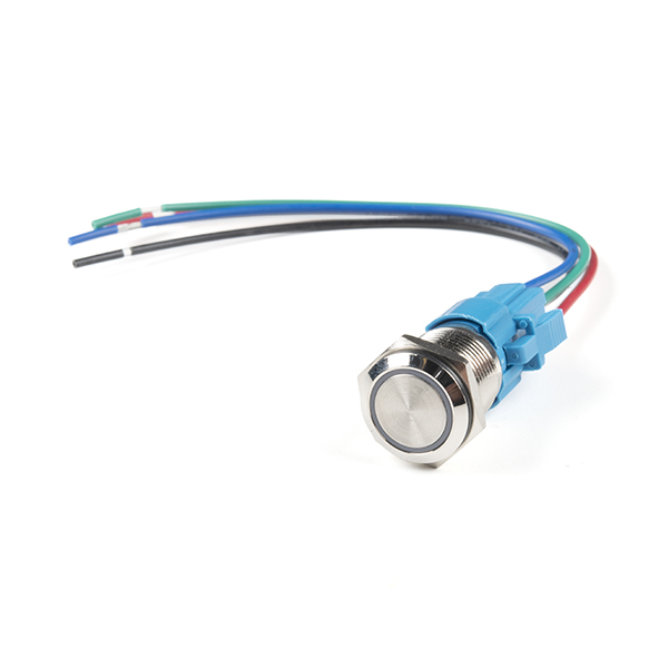
This is a perfect choice if you are in need of a heavy duty push button! These metal push buttons are a very tough, small, panel-mount momentary switch with an illuminated yellow LED ring. It is a SPDT with 16mm threading and 1mm pitch. This button is perfect for basic On/Off functions. Overall length (including leads) is 1.5" and has small solder lugs for connection. These momentary buttons are rated up to 3A and 250VAC while the LED is rated for 5-12V.
Note: The images for this button show an LED voltage rating of 5V. We have verified that the voltage range for the the LED to be 5-12V. We are currently communicating with our supplier for new documentation. Trust the branding on the button to verify your voltage requirement.
- Stainless Steel Body
- IP65 Weatherproof Rating
- Tamper Resistant
- Momentary Operation Type
- Yellow LED Ring
Metal Pushbutton - Momentary (16mm, Yellow) Product Help and Resources
Wireless Audio Bluetooth Adapter w/ BC127
December 14, 2017
Build a custom wireless audio Bluetooth adapter using BlueCreation's BC127 and add it to your old speaker system!
1 of 1 found this helpful:
Pinout
The pushbuttons (like the momentary https://www.sparkfun.com/products/11966 or latching https://www.sparkfun.com/products/11971 ) have an indication of the pinout of the buttons on the side of the plastic molding. One way to test the switch is to use a multimeter turned to the continuity setting. Here are what the pins (not in any particular order associated with the pushbutton's spades):
+ = LED Anode
- = LED Cathode
C = "Common Ground"
NC = Normally Closed
NO = Normally Open
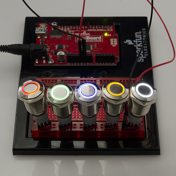
One way to light the LED on the metal push button would require you to wire it so that when you press down on the button, the led would light up. You would need 5V to light the LED ring. It can be lit up with a smaller voltage but the LED won't light up as bright.
To connect the battery to the button so that it only lights when the switch is pressed down (momentary or latched), you would connect 5V to the "+" pin on the switch. This is assuming that your system is using the same voltage source that is 5V. Then from the "+" pin, you would wire it to the normally open (NO) pin.
Another wire would be connected from the "-" pin to the C pin. The C pin would essentially be connected to your ground. So as you press down on the button, it would flip the switch and complete the circuit from the normally closed (NC) pin to normally open (NO) pin while lighting the LED ring at the same time. It might be a good idea to use a current limiting resistor (like standard 330Ohm resistor) if you are using 5V directly from your power supply. The LED won't be as bright but you also wouldn't be reducing the life of the LED. I am not sure of the electrical characteristics of the LED that is in the pushbutton.
Core Skill: DIY
Whether it's for assembling a kit, hacking an enclosure, or creating your own parts; the DIY skill is all about knowing how to use tools and the techniques associated with them.
Skill Level: Noob - Basic assembly is required. You may need to provide your own basic tools like a screwdriver, hammer or scissors. Power tools or custom parts are not required. Instructions will be included and easy to follow. Sewing may be required, but only with included patterns.
See all skill levels
Core Skill: Electrical Prototyping
If it requires power, you need to know how much, what all the pins do, and how to hook it up. You may need to reference datasheets, schematics, and know the ins and outs of electronics.
Skill Level: Competent - You will be required to reference a datasheet or schematic to know how to use a component. Your knowledge of a datasheet will only require basic features like power requirements, pinouts, or communications type. Also, you may need a power supply that?s greater than 12V or more than 1A worth of current.
See all skill levels
Comments
Looking for answers to technical questions?
We welcome your comments and suggestions below. However, if you are looking for solutions to technical questions please see our Technical Assistance page.
Customer Reviews
No reviews yet.
Why is there no wiring diagram? I'm seeing 5 wires and no clue which to use. I want to use this as an off when not pressed and on when pressed.
I don't believe it needs a resistor as long as you power the LED at 5v. Although it’s a little subtle the picture, the legs are labeled on the gray plastic housing- the outer two are + and - for the LED ring, and the inner three are C1, NO1, and NC1
Just wondering if this would be wired as off when not pressed and on when pressed??
I hope you've figured this out after 10 months have transpired but...
It can do both depending on how you wire it. Wire C and NO and it's on when pressed; wire C and NC and it's off when pressed.
I'm trying to find switches to place on a dash board of my daughters ride-on jeep to control a mini ?momentary switch on a bike light. The problem is that the switch is attached to a board on the led light housing and I'd like to control it from the dash. My question is, will these switches allow me to turn on the light and proceed through the pattern of low/mid/high/strobe or do I need a special switch? Any help would greatly appreciated. Thanks
Do you know when these will come in?
The switch has 5 solder lugs, the datasheet doesn't show a pin out, or show a sample circuit / specify if the LED ring requires an inline resistor if powered by 5v. Any chance of an RGB model ? Thanks!