- Home
- Product Categories
- Pressure
- SparkFun Pressure Sensor Breakout - MS5803-14BA

SparkFun Pressure Sensor Breakout - MS5803-14BA
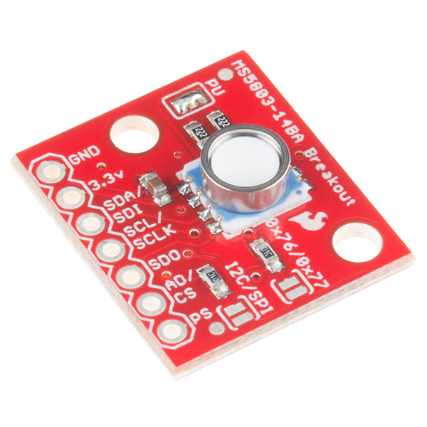
This is the MS5803-14BA Pressure Sensor Breakout, a high resolution pressure sensor with both an I2C and SPI interface. This MEMS pressure sensor measures the absolute pressure of the fluid around it which includes air, water, and anything else that acts like a viscous fluid. Depending on how you interpret the data, you can determine altitude, water depth, or any other tasks that require an accurate pressure reading. What makes the MS5803-14BA unique is the the gel membrane and antimagnetic stainless steel cap that protects against 30 bar water pressure.
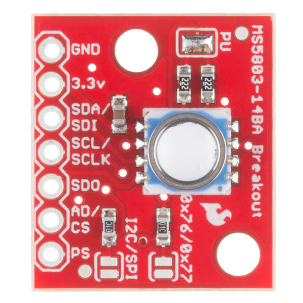
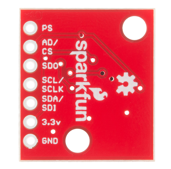
We have broken out all the pins you need including GND and 3.3V for power, SDA/SDI and SCL/SCLK for an I2C interface and SD0, AD/CS, and PS for a SPI interface. The MS5803-14BA Breakout offers a resolution range of 1 / 0.6 / 0.4 / 0.3 / 0.2 mbar. Be aware that to switch between I2C and SPI interfaces a little bit of soldering between solder pads will be required, check the hookup guide below for more information.
Heads up! While the IC is capable of outputting data via I2C and SPI, the Arduino Library and example was only written to output via I2C! You'll need to modify the jumpers on the board for SPI mode by removing solder from the pull-up resistors jumper pads and close the other two jumpers. Additionally, you will need to write a library to communicate with the MS5803 in SPI mode if you plan on using this with Arduino.
- Operating Voltage - 1.8 to 3.6 V
- Peak Supply Current - 1.4 mA
- Operating Range - 0 to 14 bar
- Resolution - 1 / 0.6 / 0.4 / 0.3 / 0.2 mbar
- I2C and SPI Interface
- Gel Protected
- Schematic
- Eagle Files
- Hookup Guide
- Datasheet (MS5803-14BA)
- GitHub (Design Files & Example Code)
- GitHub (Library)
SparkFun Pressure Sensor Breakout - MS5803-14BA Product Help and Resources
MS5803-14BA Pressure Sensor Hookup Guide
July 24, 2014
Breakout of MS5803-14BA Pressure Sensor to measure the absolute pressure of the fluid around them to determine altitude, water depth, or any other tasks that require an accurate pressure reading. This includes air, water, and anything else that acts like a viscous fluid.
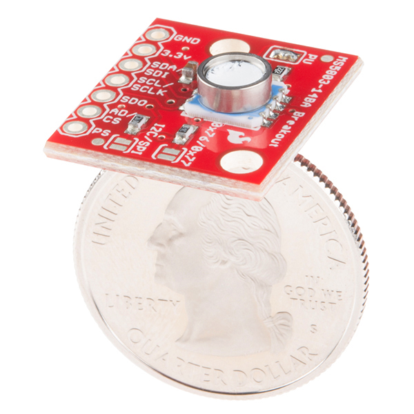
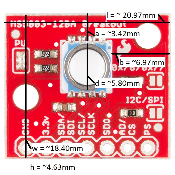
Board Dimensions
The overall dimensions for the MS5803-14BA are here:
Width (w) = ~18.40mm
Length (l) = ~20.97mm
Height (h) from back of the PCB to the top of the MEMS sensor = ~4.63mm
Picture with more dimensions:
Compatibility Issues with ESP8266 Thing and RFDuino
The ESP8266 has the same issue as the RFDuino here. It appears that for the ESP8266 (as with the RFDuino), Wire.begin() must be called after Serial.begin(), not before.
SPI Connection
Remove solder from the PU solder jumper to disable the resistors, and close both the other two jumpers on the board, the I2C/SPI jumper and the 0×76/0×77 jumper.
Core Skill: Soldering
This skill defines how difficult the soldering is on a particular product. It might be a couple simple solder joints, or require special reflow tools.
Skill Level: Rookie - The number of pins increases, and you will have to determine polarity of components and some of the components might be a bit trickier or close together. You might need solder wick or flux.
See all skill levels
Core Skill: Programming
If a board needs code or communicates somehow, you're going to need to know how to program or interface with it. The programming skill is all about communication and code.
Skill Level: Rookie - You will need a better fundamental understand of what code is, and how it works. You will be using beginner-level software and development tools like Arduino. You will be dealing directly with code, but numerous examples and libraries are available. Sensors or shields will communicate with serial or TTL.
See all skill levels
Core Skill: Electrical Prototyping
If it requires power, you need to know how much, what all the pins do, and how to hook it up. You may need to reference datasheets, schematics, and know the ins and outs of electronics.
Skill Level: Rookie - You may be required to know a bit more about the component, such as orientation, or how to hook it up, in addition to power requirements. You will need to understand polarized components.
See all skill levels
Comments
Looking for answers to technical questions?
We welcome your comments and suggestions below. However, if you are looking for solutions to technical questions please see our Technical Assistance page.
Customer Reviews
4.6 out of 5
Based on 7 ratings:
2 of 2 found this helpful:
seems to work nicely
I used it in SPI mode. I'd give 5 stars except for the fact that I had to do a little intelligent guessing to figure out how to go from I2C configuration to SPI. The description said that some other doc would say how to do it, but it didn't. It wasn't hard to guess, but that document should be fixed to give the info or else the part description changed.
Also I wish you guys sold a watertight case with a gland and o-ring to match the collar on the sensor itself.
1 of 1 found this helpful:
Easy and accurate
With the existing libraries, this was a 20 minute job to get it reading properly on my Arduino. I needed it to read pressure from a tube, so I hot-glued the bejeezus out of it and that did the trick. For that to work, I had to also seal off all the holes on the bottom of the board, basically encapsulating it into a brick of hot glue. Even so, it works great.
Very Reliable
I had this sensor running in just one hour, it's perfect for hobbyists looking for a home-made project. There are online examples on how to use it.
Does exactly what it says on the tin.
Does exactly what it says on the tin; no fuss, no muss. What more could you ask for?
An SPI library would have been nice as well as confirmation that the one solder bridge to solder was the right one, but it's really not at all hard to work out.
Great for scientific research!
Used the sensor to build a machine that dilutes gas samples stored in a glass vial. The sensor is very accurate. After calibration the machine is able to dilute gas samples with an error less than 0.5%. Very happy with this breakout board!
Worked jusf fine on an ESP32
Was very happy the Arduino support code built just find and ran perfectly on an ESP32.
I wrote a library for the MS5803-XX which is here: https://bitbucket.org/ryan_neve/ms5803_i2c It was also incorporated into the i2cdevlib at https://www.i2cdevlib.com/. After using about a dozen of these sensors (not the breakouts), I have found that the temperature readings have a variable offset, but are usually within their fairly loose specification.
Hi Everyone Has anybody developed SPI code (for arduino) for this product and would like to share? Cheers
Unfortunately, we don't have a SPI library; that is part of why it isn't documented in the hookup guide. However, we do have other pressure sensors with a SPI library.
Can someone describe to me how you wire this so that it can be submerged under water?
Has anyone been able to use two or more MS5803-14BA sensors at the same time and on the same arduino board? Tried using a multiplexer, but it seems like it needs some low level code. Thanks.
All other features aside, I assume this is much more sensitive/accurate than a BMP180 when measuring atmospheric pressure, so in terms of converted altitude readings, how much finer would the resolution be with this versus the BMP180? Does anybody have practical results they can refer to instead of calculations based on the specs? I'm asking because the BMP180 has proven all but useless for altitude measurements (same situation with the HMC533L and headings), which isn't surprising given the price, but I want to make sure the difference is significant enough to warrant the cost of the upgrade. Thanks!
Hi all, I have been using this breakout board for some time. Previously it has shown no error. But now this is what I get when I run the example code. And I have tried re downloading your library and code but there is no change. Any help is appreciated. Thanks.
I pledge to write a Linux driver for the IIO subsystem if someone buys me the hardware :)
Including python interfaces and a method naming scheme that's not a load of poo?
Neat. Super neat. A pressure transducer that can properly work with liquids.
This USGS publication has some pretty good ideas on how to apply it in a water resources context:
http://pubs.usgs.gov/twri/twri8a3/pdf/twri8-a3.pdf
A cheap (i.e. non-reliable over the long term) transducer is described here:
http://pubs.usgs.gov/of/1994/0531/report.pdf#page=10
But this Sparkfun breakout board looks way more robust in water than the Motorola (now Freescale) sensor, plus the output is digital.
The hookup guide doesn't seem to say what to do for SPI.
I think you just move the 10k to the SPI position, and remove the solder blob labeled PU (since SPI doesn't want pull-up)?
Have developed the SPI library for it? Can you please share it? I have difficulties reading via SPI Thanks
Hi there, it sounds like you are looking for technical assistance. Please use the link in the banner above, to get started with posting a topic in our forums. Our technical support team will do their best to assist you.
That being said, we don't have a SPI library. That is part of why it isn't documented in the hookup guide. However, we do have other pressure sensors with a SPI library.
Anyone had success just potting it in epoxy poured up to the stainless collar? I need to submerge in about 10 ft water. Only other interface is the wires for one-wire talk I guess they can pass out of epoxy potting safely despite rubber coating on wires?
Also, I ran into sources saying you get +-10 in water from barometric changes if you don't have an external sensor for atmosphere, anyone know a cheap one that works ok for this purpose?
Can i use this sensor in a pipe of 1-2 inch diameter?
The sensor datasheet states that it has a pressure resolution up to ±0.036 mbar and a temperature resolution up to ±0.002 °C. Is there a way to read that kind of resolution from an Arduino board?
Yes, because the output is digital you can read whatever resolution you want with the Arduino board. Check out the hookup guide or the github files for sample code.
I tried ADC_256 through ADC_4096 and in all cases the resolution is 1 °C for temperature and 0.1 mbar for pressure. I took a peek at the MS5803_I2C.cpp code and noticed that the raw pressure integer is divided by 10 (thus the 0.1 resolution) but the raw temperature integer is divided by 100 yet it does not have a .01 resolution. C++ is a little out of my comfort zone so any help is appreciated.
Hmm, I'm not quite familiar enough with this board to have an answer for you but email techsupport@sparkfun.com and they should be able to help you out.
Anyone else notice the silkscreen on the breadboard is incorrect?
Good catch, though yes, somebody must have :) While the photo shows the -12BA, as does the Eagle board file here, the production files (panelization) do show the correct -14BA silkscreen.
Who's genuinely interested in a crowdfunded enclosure for this? I've got some experience working with this sensor and sealing it to ~900ft and would be happy to work something up.
Like this one? https://www.kickstarter.com/projects/1682969561/sealed-i2c-sensor-suite-for-openrov-arduino
Sweet! This has a high enough range for DIY TPMS...
I have though about making a dive-computer for some time now, and I have wanted to use this sensor.. But the big challenge of course is the casing on a project like this. I have seen examples of people using some spray/liquipel to make the PCB itself water resistant.. I have seen it been used in a mobile USB battery for smartphones, where it is possible to submerge this into water while it's still charcing your phone.
What do you think of the idea and do you think that it would be possible to do?
i have messed with this sensor before... please search for some videos in youtube for DIVEDUINO...
is not easy to mount the "right way" you will need to have some precise machining lathe. and something better than a PCB to hold the pressure on the back.
if you search on the www.uspto.gov theres a patent that uses this sensor and they are diagrams on how they did it "just to give you and idea"
the redneck solution could be found here
http://openrov.dozuki.com/Guide/IMU-Depth+Sensor/4
Thinking about how to mount this sensor in a water tight case. http://i.imgur.com/yMcKlzJ.png Is that ok or did I miss something? Maybe a 2nd O-Ring?
this is the right way to do it.
this document will be useful for a lot of people on how to mount the sensor https://www.dropbox.com/sh/tsbrqq5waggo561/AAD6-vIg5ubB6t51cwfPD-kma
if someone wants to do an enclosure crowd funded i will be interested
this is nice. I was on the intersema website, but couldn't find any further information about how to mount this sensor. Thank you.
Good work, thank you.
I am by no means an expert, YMMV. The fluid pressure will push back on the sensor and thus on the PCB, while the screws are supposed to hold it in place. Perhaps backing up the PCB will keep the sensor from getting pushed beyond the o-ring ? I am very interested in learning an easy way to make this sensor watertight (5m would do for me). At $60, it's too expensive to just fool around with, so calling all experts !
The OpenROV guys pot their version in epoxy, ensuring that the top of the sensor case stays exposed. Then they run the whole thing flooded. Here are pictures of their assembly process; but you can visualize it as:
You can then run the wires through a sealed hole or connector into your dry zone.
Splendid, thanks Mike. Dear Sparfun : have a look at the OpenROV pricepoint. Any chance you could throw in a few pieces of acrylic (or any other epoxy-container) for the money ? Or publish a 3d-printer file that I could just take to my local printers ? Or just watertight the whole thing already (..hey, Lennon warned you : he was not the only dreamer...) ?
Could it be made to read vacuum?
Based on the spec, yes. It is supposed to be able to resolve pressures from 0-14 bar. Standard atmosphere at sea level is ~1bar. Vacuum is 0.
I plan on getting one of these sensors and my game plan is to use PVC pipe or stainless steel tubing to go down to the sensor at board level and use epoxy to encapsulate around the sensor, inside the pipe etc. up to the point that you have the gel protected port that experiences the pressure. I will then seal my pipe with a cap and use a "pressure line" to go outside of the housing that the rest of my electronics are going to go in for my underwater probe package. I am debating on if to use a diaphragm at the end of my pressure line and have the entire tubing area filled with a fluid (such as oil) so I don't have to worry about burping the line each time it submerges. If you have air in the system, it will skew your pressure readings.
Why would you have to go through so much trouble? Since it's an absolute measurement, the reference is inside the device. All you have to do is keep water away from is and seal it with a pliant material. Any pressure outside the seal will be translated directly through the seal to the device.
Well considering that I make cables that are tested to 2000 PSI for external submarine pressure hull use ... you would be amazed at how fast water will find a way into something. It really revolves around what your depth is going to be. I am looking at 100+ meters.
As for pressure being transmitted through a potting compound, that all depends on the compound and how much pressure is actually going to be seen at the sensor. The material that you are sealing it with has to "give" in order for the pressure to be felt through it. If the material is not a pure fluid then it will resist pressure to some magnitude and once again, your pressure readings will be skewed. The bottom line is you can build it however you wish, I just know what has worked for me for the past 20+ years of dealing with enclosures at high pressure and more so in seawater ... which will do some nasty things to your materials.
What would be needed to seal connections for underwater use?
I would think you could just encapsulate the whole thing in silicon once you solder wires to it for underwater use.
It looks like it'll go to... what? 150 feet at the least resolved setting, and 30 feet at the highest setting. That's awesome! Put that at the bottom of a water tank and you could accurately measure the volume of water with no moving parts whatsoever.
According to the specification sheet it should be able to handle sea pressure or some other column of water down to around 426 feet.
It can handle pressure to 943' of sea water or 972' of fresh water. It only gives readings to about 423' of sea water or 436' of fresh water.
That is correct .. I only bothered to state the measuring range. It doesn't matter how much overpressure the "sensor" can take, if you can't seal the rear from getting flooded out it is kinda of a moot point. If you are going to use it in seawater like I would want to, then you have to worry about how you are going to case it because of corrosion issues. At least they made the case out of stainless steel. It is easy to match with other metals or SS to reduce galvanic action. I might machine a fitting with an internal O-ring race to mate against the sensor wall ... the finish looks like it should be good enough for a soft seal.
From my research of the sensor, the best way to seal this is a double o-ring on the wall. My plan is to use the PCB mount holes to keep the board "pushed" onto another o-ring, just in case.
If you want to design your seal correctly, use the O-Ring Handbook that Parker puts out. These guys are the "Gods" when it comes to seals and seal design. I use their design guide all the time to get me in the ball park on pressure proof fittings. The directly link to their hand book is:
http://www.parker.com/literature/O-Ring%20Division%20Literature/ORD%205700.pdf
If nothing else, there is some excellent reading in this very comprehensive book.
Thanks for the link - yet more to take in for the project! I always went with whichever o-ring seemed "right" (and on first read-through of the PDF, it's a wonder I'm still alive! :) ) What started a simple "let's see if I can build a dive logger and gas blending set" has turned into a major educational project (not a bad thing at all). Once I have something that works, I'll be publishing all the details (for critique and edification).
Scream if you have any issues with the handbook. I have had my share of headaches with o-rings and material selection etc. but I also have plenty of years of experience with it now. My little pet project involves a package for divers too. This sensor board will take care of at least two items that I want to be able to record etc. I have to design some sensors for the other items or pay through the nose to buy it off-the-shelf. I actually got the direction for this sensor from http://openrov.com Someone has a sensor using the main component, but with this .. it is one less board I got to bother making for now.
It's almost as though you guys read my mind - I've been looking at this sensor for a dive logger/computer design!
I feel the exact same way! =)