- Home
- Product Categories
- Arduino Shields
- CAN-BUS Shield

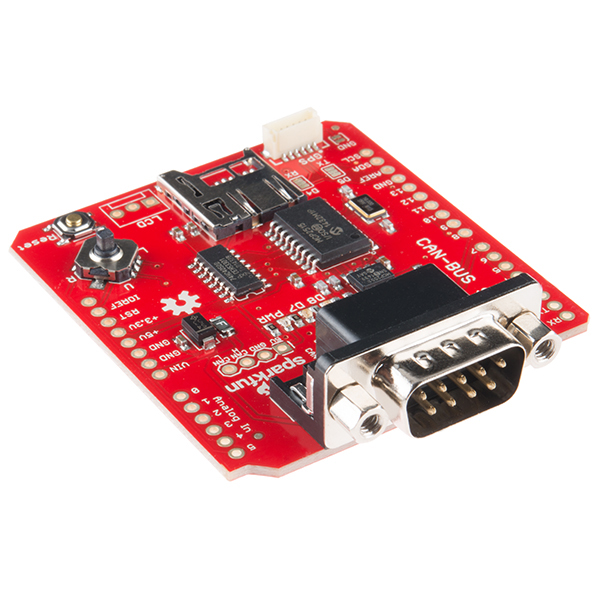
The CAN-BUS Shield provides your Arduino or Redboard with CAN-BUS capabilities and allows you to hack your vehicle. This shield allows you to poll the ECU for information including coolant temperature, throttle position, vehicle speed, and engine rpms. You can also store this data or output it to a screen to make an in-dash project.
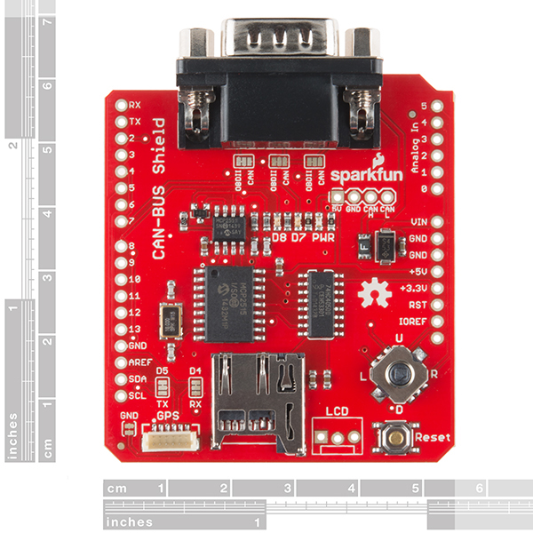
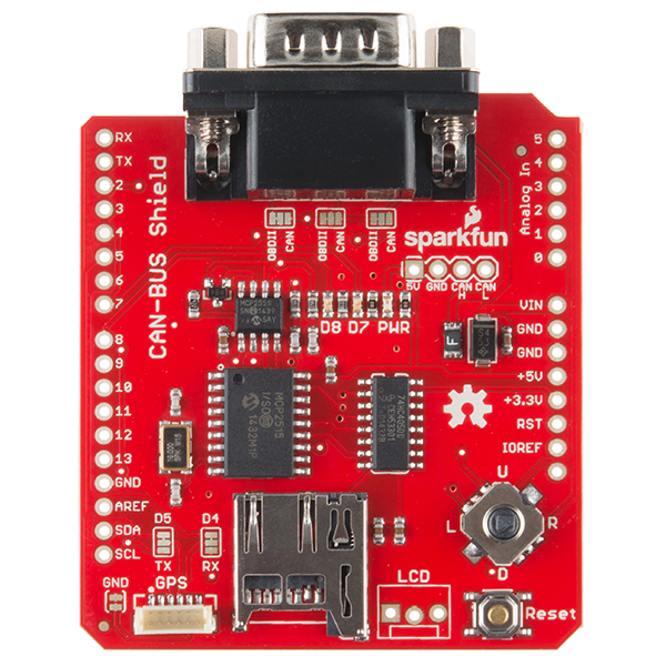
It uses the Microchip MCP2515 CAN controller with the MCP2551 CAN transceiver. CAN connection is via a standard 9-way sub-D for use with OBD-II cable. Ideal for automative CAN application. The shield also has a uSD card holder, serial LCD connector and connector for an EM506 GPS module. These features make this shield ideal for data logging application.
Note: A DB9 Cable is not included with this shield. Please be sure to check Recommended Products section below for a recommended cable to use with this board.
Note: This product is a collaboration with SK Pang Electronics. A portion of each sales goes back to them for product support and continued development.
- CAN v2.0B up to 1 Mb/s
- High speed SPI Interface (10 MHz)
- Standard and extended data and remote frames
- CAN connection via standard 9-way sub-D connector
- Power can supply to Arduino by sub-D via resettable fuse and reverse polarity protection.
- Socket for EM506 GPS module
- Micro SD card holder
- Connector for serial LCD
- Reset button
- Joystick control menu navigation control
- Two LED indicator
- Schematic
- Eagle Files
- Datasheet (MCP2515)
- Datasheet (MCP2551)
- Hookup Guide
- OBD-II Guide
- GitHub (Design Files)
- GitHub (Library & Example Code)
- Product Video
CAN-BUS Shield Product Help and Resources
CAN-BUS Shield Hookup Guide
October 8, 2015
A basic introduction to working with the CAN-Bus shield.
Getting Started with OBD-II
October 8, 2015
A general guide to the OBD-II protocols used for communication in automotive and industrial applications.
**Note for use with Mega/Due/etc.**
As a shield, this will not work directly on an Arduino Mega2560, Arduino Due, etc, because the SPI pins are moved on those boards. However, if you absolutely need the Mega, You would need to redefine the pins, and run a jumper from the shield to one of the supported pins, which you can find here https://www.arduino.cc/en/Reference/SoftwareSerial. After redefining the pins, you can always bend the pins if you soldered to the shield and reroute them similar to this tutorial => http://mcukits.com/2009/04/06/arduino-ethernet-shield-mega-hack/
Also, because our library references pins by their port name rather than by pin number or pin function, you will need to modify the library as well as re-routing pins.
Issues with cars and CAN-Bus
CAN was mandatory after 2008 on all cars sold in the US and had been widely adopted in most places after 2006. You can verify this on the Data Link Connector, by verifying that pins 6 and 14 have connections. We have a basic tutorial on that here.
**Extracurricular Activity**
If you want to try using the CAN-BUS Shield for applications not related to your car, there's a guide here that may get you going in the right direction.
**Is this thing even working?**
As a sanity check, this Instructable has some code that dumps whatever is on the CAN bus to a serial terminal. It's useful to see if the CAN Bus Shield is working.
Core Skill: Soldering
This skill defines how difficult the soldering is on a particular product. It might be a couple simple solder joints, or require special reflow tools.
Skill Level: Rookie - The number of pins increases, and you will have to determine polarity of components and some of the components might be a bit trickier or close together. You might need solder wick or flux.
See all skill levels
Core Skill: Programming
If a board needs code or communicates somehow, you're going to need to know how to program or interface with it. The programming skill is all about communication and code.
Skill Level: Rookie - You will need a better fundamental understand of what code is, and how it works. You will be using beginner-level software and development tools like Arduino. You will be dealing directly with code, but numerous examples and libraries are available. Sensors or shields will communicate with serial or TTL.
See all skill levels
Core Skill: Electrical Prototyping
If it requires power, you need to know how much, what all the pins do, and how to hook it up. You may need to reference datasheets, schematics, and know the ins and outs of electronics.
Skill Level: Rookie - You may be required to know a bit more about the component, such as orientation, or how to hook it up, in addition to power requirements. You will need to understand polarized components.
See all skill levels
Comments
Looking for answers to technical questions?
We welcome your comments and suggestions below. However, if you are looking for solutions to technical questions please see our Technical Assistance page.
Customer Reviews
4.2 out of 5
Based on 24 ratings:
8 of 8 found this helpful:
Creat Shield for the price
Ordered one to build a display to show MPH, RPM, Engine temperature and Throttle. I made some modifications to Canbus Library to show imperial measurements instead metric ones. Added a 4 line I2C LCD display and it worked great. Board also supplies 12 V to the un regulated input of the UNO. Don't forget to order the ODB to DB9 cable.
2 of 2 found this helpful:
A lot more than needed
Packs a lot of great stuff into a small design. While it's great to have all the features, I think most of it is overkill, like the GPS, Memory card, joystick and reset button and all the supporting components for these items. This board could probably be 1/8 of its current size and stack only the couple of pins it needs, leaving the arduino board free to be used for other purposes. While it is great that it can be stacked on top of the arduino or red board, it would also be nice if there was an enclosure for it. Other than that it is a great board with a lot of nice features.
1 of 1 found this helpful:
Functional, but not ideal
With the interface chip in between the CAN bus adapter and the arduino, I'm not completely convinced that I'm not losing CAN packets at the .5 Mbit rate. The micro SD card slot doesn't latch most of the time and I end up having to make a dozen or more attempts to insert a card before it finally latches. The spring-loaded slot is not good and a compression slot would be much better.
1 of 1 found this helpful:
Works great
Simple interface, got my project up and running in no time. At first I didn't think I would use the joystick, but I have implemented it to send test codes out, very convenient. I have not used the sd card slot yet. Future plans include getting the lcd attached if I can find the 3 pin quick connect plug.
2 of 2 found this helpful:
Free pins
Solid board and works great so far. I didn't need the joystick, LCD and GPS so here's the pins in case anyone needs more pins to use (you can find these out in the ECU sample):
A1-A5: Joystick
3, 6: LCD
4, 5: GPS
And pin 7 and 8 are two onboard (D7 and D8) LEDs which are handy.
2 of 2 found this helpful:
Worked for me
I used the shield for an extended CAN (J1939) application. It worked well. I would say with any of these types of products the customers would benefit from more practical examples and watered down instructions. There is a large community of people out there who only dabble occasionally with these products or don't because of poor documentation and examples.
1 of 1 found this helpful:
Very easy to use
It seems standard libraries for the MCP2515 CAN transceiver work best with a 16MHz clock. Many CAN-BUS interfaces have an 8MHz crystal, which I have found difficult. This Sparkfun shield has the 16MHz crystal, as well as working libraries and examples. Paired with the Redboard this is the simplest set up I have found for reading non-OBD-II CAN-BUS systems.
1 of 1 found this helpful:
Works Great with J1939 too
Had to get a book on J1939 and add the 120 ohm resistor across CAN-L and CAN-H, then i could get bus response. Reccoment Wlford Voss's books for J1939 as documentation is sparse on the WEB
1 of 1 found this helpful:
Good for CAN-BUS tinkering
This is a great place to begin CAN-BUS tinkering. The DB-9 is pre-wired to work with the OBDC-II cable so it's easy to connect to a vehicle. The sample code is a bit weak and lacking documentation. There are better examples elsewhere online. You need to be careful that you pay attention to ALL the pins the CAN-BUS shield uses as it contains more than just the CAN-BUS interface - i.e. it has a memory card interface, GPS interface, and two LEDS on D7 and D8. Overall, it works well and so long as you are cognizant of how it's connected it's easy to get data from a CAN-BUS or to send data over a CAN-BUS.
1 of 1 found this helpful:
Finally something that works
I wasted many years on Chinese OBD products for Arduino. Inevitably I ran into some kind of a connection problem. Inevitably, I couldn't get any support (they just don't reply). This thing works. BTW, it seems that the cable connection to your car's OBD port is sensitive to electric interference. I removed the DB9 connector and I used a short, shielded cable, connecting only GND, CAN-H and CAN-L (2 wires + shielded ground)
7 of 8 found this helpful:
Nice features, missing some basics
I like how many things are packed into it. Price is very fair. Really like the option to cut the board and make the DB9 connector use pins 2 and 7 like any professional CAN equipment uses. This option is why I bought the board. I really didn't like that the Seeed CAN shield didn't have this option.
Cons: Chip select pin can not be changed. The library doesn't look like it has a simple option for this either. Switched to the coryjfowler library. I really wish you would have at least done what the Seeed CAN shield did and give me one other pin as a choice. Had to add 120ohms to make it work on a bench. The Seeeeeed shield gave me screw terminals to do this, but not this board. Also, wish that I didn't have to modify the board to make it work with industry standard pins 2+7 on the DB9. Lastly, the ad doesn't mention that the shield is completely bare. Please at least update the listing notes to suggest that you buy headers for it.
This board is probably better for the person that wants all the extra features, but if you just want a CAN shield and use CAN regularly, I wouldn't buy it if you already have a Seeed shield. You're better off hacking up the Seeed board to support pins 2 + 7 if you already own one.
4 of 5 found this helpful:
Great learning project for CAN interface
I used it for interfacing with a 125k vehicle CAN bus. Soldering the headers were fairly easy, but I struggled with the 9-way OBD-II to CAN conversion. I'll agree with another review when it come to making pins 2 and 7 the standard Lo and Hi. Let the few who need OBD-II struggle with the conversion.
3 of 4 found this helpful:
documentation poor
Documentation for this device seems to be lacking. I ended up purchasing a pican shield for the pi2.
3 of 4 found this helpful:
kinda ok
After fighting with the libraries for almost a week i finally got it right to retrieve some usable data from the car. I switched to another library to confirm the speed at which my car was sending data. i still couldn't see "human" readable data until i found a fork of the sparkfun library, after some modifications to the sketch i was able to use it. As for the shield itself, i would have preferred if it was shipped with headers. i only realized this after my delivery and needed to place a second order only for the headers.
2 of 3 found this helpful:
Connected great to my car's canbus
With the OBD2 accessory cable an an Uno, I was able to eavesdrop on my car's CAN-BUS.
0 of 1 found this helpful:
Good for DIY car stuff
You can use the OBD2 cable to interface with the car ECU (brain of the car). Works nicely when an engine light is on...then you can fetch diagnostics.
0 of 1 found this helpful:
DB9 <-> OBD II cable?
Is there one of these commercially available? I can build one but am having trouble finding a pigtail for the automobile side. Thanks in advance for any help. mcb
BREAKING NEWS: Found them, they weren't in the recommended products list
0 of 1 found this helpful:
This shield have a lot of features (like SD card socket, GPS connector) that enables to create awesome projects.
0 of 1 found this helpful:
Epic card
My dream comes true with this shield. I've a project on my car, and this is the best solution to realize this dream, cheapy. I used uSD card on it, works perfectly. I have an Arduino Uno to do some tricks.
0 of 1 found this helpful:
The product is excellent
I have not yet test it, but I think the product is crazy ;) excellent.
I will test it next month or at the beginning next year.
Best regards Hakan orcan (Germany)
0 of 1 found this helpful:
Easy to use.
I only used the CAN interface to debug another project..
0 of 1 found this helpful:
Great for learning to "hack" my car, but one problem
I've had one of these for several months now, and I love using it to gather data from my car's OBD-II port. Learning which signals to look for and how to scale them appropriately took a little time, but that was part of the fun. The main concern I have regarding this board is the amount of heat that the Arduino's on-board 5V regulator has to dissipate because the incoming power is from the car's batter (generally >12V), even for low current draw applications, such as the Blink.ino program. It would be great if future versions of this board included a separate 9V linear voltage regulator to share some of the power dissipation.
Works correctly with CANBus interface on a Smart Electric Drive
I bought this to build a unit of an open-source Battery Management System diagnostic interface for a Smart car electric-drive unit. The DB9/OBDII connector cable (CAB-10087) that Sparkfun sells correctly plugs this shield into the CAN signal pins on the car's diagnostic connector, also allowing the 12V power from the car to power the shield and Arduino.
I need a version of this product that has an OBD connector (the regular 16-pin connector) instead of this DB9 connector. Does anyone where I can find that?
For those interested in using this CAN-Bus Shield for accessing vehicle CAN-Bus data, this diagram illustrates the format of the SparkFun_CAN-Bus_Arduino_Library message structure for multi-frame (ISO 15765-2 protocol) CAN-Bus message exchange.
Hi, I am trying access a battery unit, that uses CANOpen protocol. Would like to understand the change that is required on the code to use CANopen protocol.
Hello, Can this communicate over SPI with a 3.3V processor ? Thanks.
This shield operates at 5 volts so you would need a logic level converter between the shield and your processor to avoid damage.
Hi, I plan on using the CAN bus for a project, but I will also require I2C for another part of the project. Does this shield limit the ability of the SDA and SCL pins?
I used two of these shields to communicate with each other. Without adding the 120-ohm termination resistors from CANH to CANL, the boards would not communicate properly at all. It would be great if the shield added a solder jumper to add or disable a termination resistor.
Is it possible to use an extended 29 bit ID? According to CAN 2.0b, which this board says it is compatible with, extended ID's are possible from 11 to 29 bit. However, I can't get the transmit function to accept a 29 bit ID.
I like the board and it works great for me however I'm not using the Joystick, Sd Card, LCD, GPS, DB9 or the two LEDs. I find using some of the pins used for these causes some issues.
Can you guys please release a bare bones Canbus Shield.
I got stuck troubleshooting my project for weeks because I used Pin#8 which is just an LED pin however somewhere deep in the header files the CANBUS shield is sending signals to that LED outside of the Arduino IDE.
INIT OK BUT NO VALUES
Hello everyone I got an issue, i am already followed steps of hook up guide I did all connections at pin headers just I didnt sold LCD pins and 4 hole pins (5V hand CanH CanL). I am already use db9 cable but when I am run any demo code example from library that sparkfun released I am just get only INIT OK while db9 cable is not even plugged at vehicle ,without any other clue. If anyone knows please help .
Hi, Can I please know the reason for using MCP2515 CAN controller? Why cant the MCP2551 CAN transceiver can be interfaced directly to the Arduino using the TX and RX ?
For the most part the Arduino is connected directly to the MCP2551. From what I can tell the RX/TX on the MCP2551 is the CAN interface which is connected to your CAN device. The MCP2551 is connected to the Arduino over SPI the rest is just bonus useful stuff (SD slot, GPS connector, LCD output). As for why we chose this chip, that's a 7 year old question. It looks like we originally made this board 7 years ago as part of a collaboration so I'm not sure anyone knows anymore.
Can't get ik working yet. I have 2 CAN bus shields, each on an Arduino Uno. So i do not use it for my car, just regular CAN bus. I changed (soldered) the jumpers to use CAN. I have put a 120 Ohms termination resistor on each shield, between CAN Hi and CAN Lo. On one Arduino I use the Write sketch, on the other the Read sketch. Nothing is transmitted. Both sides say: "Can init OK' What else can I check?
UPDATE: It works now. With a CAN bus tester I found that one shield was working, the other not. That's why they could not see each other. On the one that was not working a corrected a soldering error (I short circuited one of the CAN jumpers). Now they talk happily to each other...
Hi! First of all, great product! I'm trying a setup with an Arduino GSM shield, on top of CAN bus, on top of Arduino. Without the CAN bus, it works fine; with it in the middle, it sometimes does, but sometimes not. The GSM only uses pins 2,3 and 7. Am I missing something? Also, can the CAN bus inserted into an OBD II port power all the three boards? Is it safe to try that?
Please take a look at the schematic for the CAN shield. You're getting intermittent behavior because the CAN shield also uses pins 2 and 7. As far as power requirements, you should look at the current draw for your particular shield, and verify which pins it is pulling power from.
Thank you for the quick response, it all makes sense now. I am not good with schematics, but it was time to learn anyway. I think I could get around the issue with pin 2 by modifing the library defaults.h MCP2515_INT value and using some jumper to switch pins. I can see that pin 7 is only used to light up an led, so that shouldn't be any cause of concern. Am I on the right track here?
You got it! Best of luck hacking :)
Have you thought about putting a resistor circuit on the joystick/buttons so it only takes up one analog pin instead of 5?
Go the example working fine using the ecusim 2000 and the example code.
But now I need to transition to an industrial can environment using this shield: Would someone please explain: 1) How to do 1Mbps instead of 500 kbps? The example lib does have CANSPEED_1000 defined.
2) Need to use the DB9 connector. How to change the jumpers to use normal CAN signals instead of OBD-II signals on the DB9 connector? Is there some soldering/desoldering to do?
Thanks!
Hi guys, I would like to know if it is possible to get the accumulated mileage information by using this shield. I want to get this information and send it to a computer or mobile.
I'm having pretty good success with this shield but I'm seeing some "noise" using the ECU Demo. The data seems to be accurate 90% of the time, but it'll occasionally switch to another data type or will jump to zero. The prefix here is a millis() printout.
6042: 849 rpm 6059: 849 rpm 6075: 849 rpm 6091: 0 g/s ... 6430: 0 g/s 6444: 1800 rpm 6461: 1823 rpm 6478: 1823 rpm
Is this something I should look into in the library or sketch, or could there be some noise or inconsistency from the car? I'm trying to narrow down where the fault lies.
Basic trouble shooting step would be to check one item at a time - I'd verify you don't have any bad connections on your shield, and then verify there's nothing weird reading on the cable and in the car connector. After that, the library would be the next step to check.
I have connected this CAN-BUS Shield to OBD-II connector of a 1996 Nissan Maxima. When I power up the board(SparkFun_CAN_Demo) I get "CAN Init ok" followed by the selection menu, but it does not prints anything after entering anyone of the option. It prints the selected option but no data. Am I missing something?
Are you using our DB9 to OBD-II cable? If not, you may need to double check your pinout on your cable to ensure it's connecting pins 6 and 14 from the data link connector on your car to the appropriate pins on the CAN-Bus Shield.
Yes I am using SparkFun DB9 to OBD-II connector.
Hmm. It sounds like you need a bit more in-depth debugging than we can do via comments. Please contact techsupport@sparkfun dot com with your set up, the code you're using, and any errors you might be getting. They will be able to assist you more in depth, and if there is an issue with your board, get you a replacement.
Ok thanks a lot. I will contact tech support.
Hello Toni_K,
I just tried the same setup in a different car(2010 Hundai Sonata) and it worked perfectly fine. The problem was with my old car.
Thank you for all the support. I would definately like to buy you a beer to honor the beerware..!!
Did you ever get it working with your older car? If so, how did you do it?
Hey Arodd2000, I did not investigate what was the issue with getting CAN data on my old car. I think it must have been malfunctioning as I used a different diagnostic tool to check CAN messages and it was responding to a very few request messages. Something like 1 in 20-30 request messages. Hope this helps you.
Glad you got it figured out! If you ever make it out to Boulder, I'll certainly take you up on that. In the mean time, happy hacking!
How would I edit the CAN library to work with an AEM EMS-4?
Does this shield support K-Line?
K-Line, or pin 7, is broken out to the CAN-H header if you have the jumper configured properly. Please take a look at SJ4 in the schematic to trace this out. However, the example code is written to support CAN-H on that line. If you'd rather use a different protocol, you will need to find or write your own example code supporting this.
When I bought the shield I downloaded the schematic. There isn't any SJ4. There is instead in the latest schematic but I suppose it is relative to another rev of the shield.
https://s5.postimg.org/mqfoj7siv/shield.png
Anyway an example code for k-line would be really appreciated if there is any chance to use the shield also with this protocol of communication.
If you have the older version of the shield without SJ4, then you will need to cut the traces and use jumper wires to attach the K-Line to the CAN-H line on the chip.
Regarding the code, we don't currently have any examples of that, but you could rewrite the library to match the K-Line protocol message structure in place of the CAN message structure. There's a good basic summary here, and there's also this Arduino thread which may be helpful for you as well.
Guys, I need some serious help. I am using this shield to communication with my Honda 2006's ECU. But whenever I connect the shield with the car and run the demo code it only gives one response "CAN Bus Demo" and nothing else. Any help please?
Please contact tech support. It sounds like there is an issue with your shield or circuit, as the demo code should at least print out "CAN Init Success" or "CAN Init Fail". If you aren't getting either of those, your shield and board are likely not communicating.
yes, this is the problem. The shield is not working, even the demo code doesn't work. I'll definitely contact the support team.
Will this work on any CAN-BUS? I need it for an industrial application, not automotive. Thanks
I am using the default sketch for the GPS_DEMO (running a 506 gps) and the following hookup Arduino Mega : SPI (50-53) <
> Shield : GND, 5V, 3.3V, RESET, IOREF / Arduino Mega : Digital 4&5 <-> Shield : Digital 4&5 The GPS gets a fix, but it never outputs to the serial. Am I missing something?
Probably something to do with the software serial pins on the Arduino Mega if you are not able to view data through the serial monitor. Check your pin definitions and the limitations of the Arduino Mega Pins if you haven't already => https://www.arduino.cc/en/Reference/SoftwareSerial .
Also, check to see if you have satellites in view. If you are in a building or in a noisy environment, you won't receive a signal and not get a solid fix.
I am using MEGA R3 with this CAN-BUS Shield. It seems it is not able to initialize CAN.
I can either "CAN-Bus Demo" or Below reply.
CAN-Bus Demo Can't init CAN Please choose a menu option. 1.Speed 2.RPM 3.Throttle 4.Coolant Temperature 5.O2 Voltage 6.MAF Sensor
I did connect the SPI wires as suggest by Toni.
Double check that you've updated the pin definitions in the code to match the new wiring, especially the CS pin. If those haven't been updated, your Arduino is trying to initialize the CAN-Bus using the wrong connections, and you won't be able to initialize the IC.
I'm planning to set up CAN communication with the Arduino Due and need a CAN shield/breakout board. The operaing voltage of the Due is 3,3V. Is it possible to connect the shield to the Due?
It's not recommended. The CAN-Bus shield mostly operates at 5V, but it also handles 12V coming in to the board when plugged in to a CAN port.
Is this board fully compatible with Arduino Mega 2560? Which pins it uses?
This uses the SPI pins from the Uno footprint by default, so it is not plug-in compatible with the Mega. You will need to run jumper wires from the shield's pins to the Mega's SPI pins.
Is there an image that shows where to hook up the jumper wires?
You can find them on a lot of folks' projects, but these are the basic pins you'll need to identify on your board to connect.
MEGA SPI: 50 (MISO), 51 (MOSI), 52 (SCK), 53 (SS). UNO SPI (this will also be the shield footprint): 10 (SS), 11 (MOSI), 12 (MISO), 13 (SCK).
Does it support J1939?
There are some example projects with the libraries updated to work with J1939, though our library is not currently set up that way. Check out one example here.
Could this board be used to emulate the vehicle side? Not the scanner?
You could send out raw CAN data simulating that coming from the vehicle from the CAN +/-, 5V/GND pins broken out on the board. However, you'd need to do a lot of code modification for that to properly simulate the vehicle functionality.
You say this is new. What is the difference versus the previous part DEV-10039? Thanks.
It has the Uno R3 compatible footprint, jumpers to configure the DB9 connector for different OBD-II cables, and general production improvements for manufacturing.