- Home
- Product Categories
- RFID Readers
- SparkFun Simultaneous RFID Reader - M6E Nano

SparkFun Simultaneous RFID Reader - M6E Nano
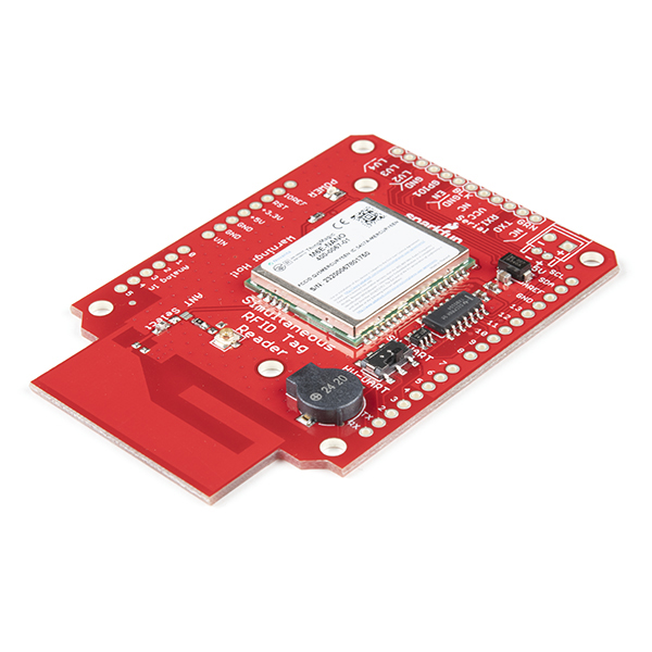
The SparkFun Simultaneous RFID Reader is an Arduino-compatible board to get you started with the M6E Nano UHF RFID Reader. Radio Frequency Identification (RFID) is becoming popular everywhere for tracking practically everything. Whether you want to get started by adding an RFID reader on your toolbox with tags on all your tools or allowing access to the tree house for your secret society meetings, this board may be for you!
With the Arduino shield footprint, you can connect this directly to an Arduino-compatible board, or a different microcontroller. You can also connect directly to your computer using the FTDI header on the board and read data using the Universal Reader Assistant.
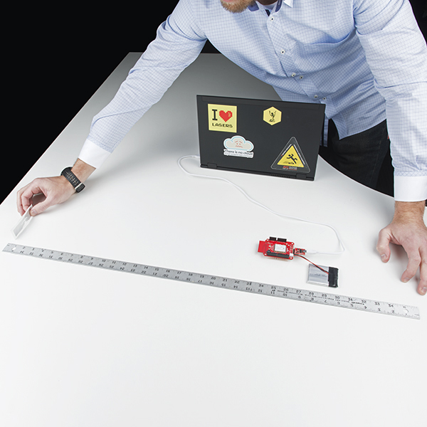
Once you've started, this board will read EPCglobal Gen 2 tags (see Recommended Products) at up to 150 tags per second. Writing of tags is also possible at 80msec standard write. The board has adjustable power output from 0dBm to 27dBm, meaning that with the correct antenna you can read up to 16 feet (4.9m), or 1 to 2 feet with the onboard antenna.
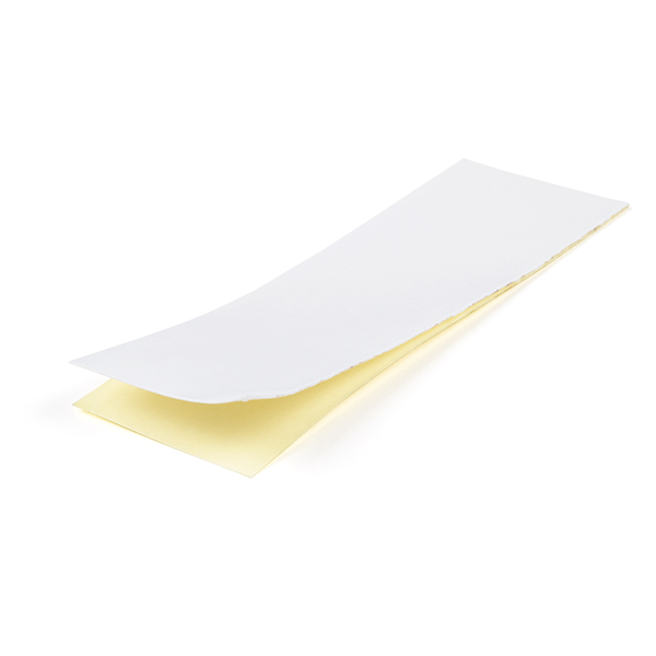
Note: Your reader ships with a piece of gray, nonconductive Thermal Gap Filler to help with both heat dissipation and to cover the exposed ground plane (to prevent circuits from shorting against it).
Note: The FTDI Cable products are known to be incompatible with the Simultaneous RFID Reader. Please use the CH340 Serial Basic Breakout or other serial interface.
Warning: Ensure that personnel do not stand in the radiation beam of the antenna unless they are more than 21cm away from the face of the antenna (to adhere to FCC limits for long-term exposure). See Datasheet for more information.
Need a custom board? This component can be found in SparkFun's À La Carte board builder. You can have a custom design fabricated with this component - and your choice of hundreds of other sensors, actuators and wireless devices - delivered to you in just a few weeks.

- EPCglobal Gen 2 (ISO 18000-6C) with nominal backscatter rate of 250kbps
- Separate read and write levels, command adjustable from 0dBm to 27dBm in 0.01 dB steps
- 0.84W in ready mode
- 0.00025W in shutdown mode
- Up to 150 tags/sec to read 96-bit EPC
- 80msec typical for standard write of 96-bit EPC
SparkFun Simultaneous RFID Reader - M6E Nano Product Help and Resources
RFID Basics
February 23, 2017
Dive into the basics of Radio Frequency Identification (RFID) technology.
Simultaneous RFID Tag Reader Hookup Guide
February 23, 2017
A basic guide to getting started with the RFID Tag Reader breakout and how to read and write multiple RFID tags over multiple feet!
Reading a Pile of RFID tags
There might be some interference if the M6E Nano RFID reader is trying to read a pile of RFID tags. This can cause issues reading a few tags that are directly on top of each other. It would be better to spread the tags at a certain distance from each other or move the RFID reader around to get a clear read on all the tags in range.
Comments
Looking for answers to technical questions?
We welcome your comments and suggestions below. However, if you are looking for solutions to technical questions please see our Technical Assistance page.
Customer Reviews
4.4 out of 5
Based on 27 ratings:
3 of 3 found this helpful:
Everything I needed
This was exactly what I need. I am making this review to encompass and answer every question I was having at the start of my project so if someone is trying to do something similar they can have more of their answers answered. My project that I used this for was to use python in a Raspberry Pi to interface with this reader using an external antenna up to a distance that would cover a normal traffic lane. My project would essentially be a Time-Trial RFID Timing System.
It worked, I have all the parts that I used from Sparkfuns site listed at the bottom of this review.
Preparing the board for use with internal antenna First, when I ordered these parts I did have to solder on the connectors. Another thing to note also, The serial USB breakout that I ordered did not have all the matching labels on the reader (TX0 and AX1 were switched) but matching BLK to BLK and GRN to GRN is the correct way of connecting it for reading through USB. I also bought the 6AH Lithium Ion batter for external powering, I am sure smaller battery options are viable I just needed more than an hour of run-time with mine at full power.
connecting the board with the Raspberry Pi 3b+. Utilizing the serial breakout, I physically connected this with a simple USB to USB Micro cable. Programmatically connecting the Pi to this unit was one of the more difficult parts. For me, I had to make sure the latest python version was installed along with the python-mercuryapi python wrapper. For simple non-GUI related programs using this you can get away with python 2.7 but I wanted to use the tkinter python GUI library for this project so Python version 3.7 or later was easiest to work with. I had to google how to find the correct reading tty address and for my pi with this connected it was TTYUSB0. It might be different for others but this was mine.
Using the internal antenna When starting if you are not using external power, you have to set read power to 5 dB otherwise the unit will brown out and become unresponsive until you restart the read attempt. The successful read distance I was getting with both external power and the USB set up for powering was about half a foot. I have a hunch this was because allowing the USB to provide power to the system was producing noise and degrading its read accuracy. That will be discussed in the external antenna portion.
Preparing it for an external antenna. First, follow the directions listed in the guide they provide for setting up external antenna. Second look at the schematic. I spent a few extra minutes removing solder unnecessarily because I thought I had accidentally bridged a connection between SJ1 and SJ2. These two connections are bridged internally so as long as SJ1 is desoldered and no longer jumped and SJ2 is jumped with solder, that is what is necessary. When using the WRL-14131 Antenna that was recommended with the USB and Battery providing power, I was only getting a read distance of about 7 feet. After carefully severing the power jumper to the USB as listed in the guide using and Exacto knife, I was able to get read distances over 15 feet which to me is a great success. I believe the noise introduced by USB power significantly degrades the range of the unit with both external and internal antenna. So if you find yourself lacking distance it is something to consider.
PARTS I USED LIST: SEN-14066, WRL-14147, WRL-14131, CAB-14132, WRL-00662, DEV-14050, PRT-00553, PRT-09749, PRT-10217, WRL-14147, PRT-13856
Parts I used not listed on Sparkfun: Raspberry Pi 3b+, USB to USB-Micro cable
1 of 1 found this helpful:
Great product
It works as advertised. Range was not better than 8 feet with the recommended antenna at max power, however changing the antenna to the 80mm ceramic the range improve above the 18 feet. Thanks Sparkfun and Vince5 for your posting.
2 of 2 found this helpful:
I can read a tag from over 5 meter away using a 80mm ceramic antenna.
3 of 4 found this helpful:
Everything is great except switching to external antenna
This is mostly a great board. It works as advertised, and I've had no trouble using it. (I'm using it with Mercury API on a Raspberry Pi.) Based on that, I would have given it 5 stars.
However, the mechanism for switching from the internal to the external antenna leaves a lot to be desired. The solder jumpers that need to be changed are very small, and I ended up ruining my first board trying to switch to the external antenna. I bought a second one, and succeeded in enabling the external antenna on that one. But, I am cranky that I had to spend $400 instead of $200.
Also, it would be nice to be able to switch back and forth between the internal antenna and the external antenna. Some sort of DIP switch rather than a solder jumper?
Now that I've got the external antenna working, I'm a bit disappointed in its performance. I've sometimes been able to read tags 8 feet away, but other times I've had trouble reading tags 3 feet away. And I haven't been able to pick up tags at anything close to the advertised 16 feet. (This is at maximum power, of course.) Also, if you want to read the user memory, the tag needs to be closer than if you just want to read the EPC.
2 of 3 found this helpful:
Game Changer For Makers
The reader works great, even without the antenna the range is better than any other hobbyist RFID devices I've found for this price. The supporting documentation is very thorough and helpful. If you want to add a bigger range to your rfid projects, buy this.
1 of 4 found this helpful:
Arduino library not working
the board works well with the supplied thingmagic software, however the arduino library does not connect to the board.
No support from sparkfun for 4 days so far, may as well buy the chip diectly from thingmagic and bypass the sparkfun board.
Hello!
Sorry about the delay for support - the only case I see that you have open is #220744 that was submitted 23 hours ago. While our technical support team is very dedicated to offering the highest level of service that we can, at the same time they are a small department of 7 technicians that handle cases in the order in which they were received.
Well designed and documented
Sparkfun went a long way to make this approachable to makers and hobbyists. First, it is an Arduino shield so much of the hardware connecting is taken care of out of the box. Second, their tutorial was thorough and the included examples made reading the first tag a simple matter. Third, this was on the low-end of the price scale for UHF modules but it used a high-end chip. I used an Arduino UNO clone to start and had no troubles. Don't forget to buy the Interface Cable RP-SMA to U.FL (WRL-00662) if using the external antenna, it was not listed in the Hookup Accessories.
Missing the cable for the larger antenna
It's missing the cable for the larger antenna, and it's NOT listed as 'recommended' have not tested it because of this. But it's a very nice shade of red!
Sorry about that! It looks like the two cables you need to connect the external antenna are part numbers CAB-14132 and WRL-0662. These should also be listed in the hookup guide as well.
Doesn't work - pressing pro use
This expensive RFID reader doesn't work either with the standard Arduino Uno as described in the tutorial or with a serial Rx/Tx module to communicate with it. Does this RFID reader needs to be flashed ? Would REALLY appreciate some quick and pro help
We're sorry you're having trouble. Please contact our technical assistance team for help with your board. We do test these before shipping with a RFID tag so you should have received a working unit. Our support department should be able to get you up and running.
Good quality
Works as exprcted, easy and fast. I owned other pcb unit, programing is easy and support is best fit for me.
Good - but room for improvement
I have two gripes with this component. Firstly, the range without an external antenna is measly: you'll be lucky to get 6 inches. Secondly, it doesn't support multiple antennae.
That said, it does work; you'd pay at least double for a Simultaneous RFID Reader elsewhere; and no one else - to the best of my knowledge - makes a Simultaneous RFID Reader which slots in so well with an Arduino.
excellent multiple RFID reader
It worked exactly as it described, was able to read 10 tags simultaneously. excellent RFID reader
Works well with minor issues
From an RFID, programming, interfacing perspective it is wonderful, worked well in every way that matters. I was able to easily read a pile of 30 or so tags simultaneously. The most difficult part, for me at least with vision issues, was switching to the external; antenna - more "generous" sized pads would have been appreciated for something the end user would likely need to rework. Clean power is essential for use at higher power levels, as is a proper heat sink for continuous usage. Worked great. Would recommend.
Made it so simple!
Got this and the antenna, and everything worked great, could read tags across the room!
Great board with excellent documentation
Setting this shield up with an Arduino Uno was my first arduino project and the hookup guide was excellent. The unit works as described and the range is even quite good with the onboard antenna. Really can't complain about much on this thing. Thanks Sparkfun!
Works exactly as intended.
Works great, and SparkFun has great documentation available, as well as libraries and code examples. My only advice to buyers is to make sure you read the setup documents, especially if you're connecting and external antenna. There's some quick soldering of jumper pads required, but they have it all step by step with illustrations, so it should be quick and easy. Overall this reader works great!
Excellent but pricey RFID reader/writer
Have worked with this extensively for a project and find it very reliable and fast, once you get past the software learning curve. Range is more than I need, 2 feet plus with 3" adhesive tags. For my application I needed non-blocking firmware so had to re-write major portions of the posted arduino library.
Work well 👍🏼
Work really well, only thing missing is a physical jumper to switch between the onboard antenna and the external antenna. Solder jumper are a bit annoying to deal with during developpement.
Superior Codebase for the M6E
I started my RFID integration project by buying the M-series chipset straight from the manufacturer in the form of a dev kit and trying to get things working with their C code base. It was a huge waste of time. The code base provided by SparkFun for this breakout board was significantly better written and documented.
The only bad thing I will say about this breakout is that the linear slot antenna printed on the board is not worth even attempting to use. If you're trying to do anything with RFID at a range that's greater than ~1", save yourself some trouble and go straight to using an external antenna.
0 of 3 found this helpful:
Major struggle to use this reader
After installation of the Universal Reader Assistant utility under Windows-7, and connection via a known working FTDI USB-to-Serial controller, the software will not connect to the device. It just hangs and so is useless. This has turned into an expensive "boat anchor".
Works great
No issues what-so-ever. I followed Sparkfun's tutorial (well written) and was reading RFID tags in a short time. Using windows 10 with Arduino.
Pretty amazing range
Longest range I have ever used on an RFID. Works a bit strange sometimes, but sparkfun tech help gave me some advice. Used in a large art installation. Going to purchase a second one for a zoo project!
Stopped responding in 2 Hours, but it was our fault ;)
Engineers gave wrong voltage to the board. New Piece worked really well. I am adicted to this site now. Previous Comments- "I am not harsh but unfortunately, it worked well and produced good results for 2 hours and suddenly the board is dead, no response at all. I do trust this company and product. I just reorder it. Hope this (new piece) will live way longer than previous one. Also when we order from India, we end up paying 100% import duty that is a bit hard.
I am willing to come and change this rating as soon as I receive the latest order and it works for me. "
I'm sorry to hear that! Please contact our technical support team for help with this. They will be glad to help.
Great start
I'm using the SRTR to count laps for a charity walkathon. So far, I've soldered the header for Serial Basic, connected them via USB to my Ubuntu machine, and programmed with a python wrapper to the Mercury API (see github). Tags are read and written successfully using the PCB antenna. I'll try the high-gain antenna soon. I appreciate SFE comments on power and thermal management, as those will definitely be a concern for my project.
The firmware version of the M6e Nano is 1.03.02.4A. The current version according to ThingMagic's website (1) is 1.7.1 ("CRITICAL firmware release for the ThingMagic Nano modules. (Prevents issue of CRC error with no method of recovery.)") of Dec 2016. It would be very kind of Sparkfun to provide the recent firmware as the current one may permanently kill the board!
(1) http://www.thingmagic.com/index.php/manuals-firmware#Nano
It appears that the latest batch of readers that SparkFun is now shipping have the 1.7.1 firmware preinstalled. (Specifically, 01.07.01.02.)
An idea to allow mounting a heat-sink to this product while still being able to use it as an Arduino shield: Put stackable headers on your UNO-compatible (best if you can get one without any header sockets pre-installed to avoid the hassle and potential damage of desoldering). Then you can stack this board under the Arduino.
I have recently purchased the Sparkfun Simultaneous RFID reader (which uses the ThingMagic M6e nano module). I have been using it with an Arduino Uno and using the Sparkfun Arduino library.
It works well for reading tags, but it tends to read tags randomly (or maybe it reads the tag with the strongest RSSI). So, if I had 5 tags sitting, it would tend to return the UID of 1 tag many many times, and occasionally show the presence of others.
For my project, I would like to be able to ask the reader to look for a specific tag, given it's UID. After searching through all of the documentation provided by ThingMagic, I can see that this module can carry out this task easily (by applying and using filters), but the Arduino library does not support this kind of capability, and I'm really struggling implementing this myself.
Is there anyone who has looked at this before and achieved any sort of 'specific tag read/write' operations with this module and Arduino?
Thanks.
Having the same issue here. Any updates regarding this?
I used the nano as a Arduino shield. Tried Example1_Constant_Read and Example2_Read_EPC, It is stuck in "setupNano()". It is also showing ??? texts thats like the font is missing. any help?
Through Water? Anyone tried using one of these to read an RFID tag through a few inches of water? Or with the external antenna (Antenna on the outside of a tank of water, tag inside the tank)? Range?
Hi All,
Having a little difficulty getting this going would appreciate some help.
I have the reader hooked up to my windows 10 laptop using the serial basic breakout and a USB cable.
I have installed the univeral reader assistant software. The setup is fine it, it shows M6e nano in the corner so I know that it has detected the board correctly.
When I hit read in the software I hear the windows USB disconnect tone and when I wave my tags in front of the reader I get no reading. If I stop reading then the software appears to have lost connection to the reader, I get a error saying 'specified port does not exist. Check supported protocol confuguration in readers hardware guide'. If I press read again nothing happens, I need to disconnect and reconnect the device to do another read.
I'm making sure to keep the read and write power <5dBm as per the instructions.
Any ideas? The USB dissconection tone I'm getting when I press read is making me think the device is disconnecting itself for some reason.
Thanks, Adam.
*Update: I've managed to get the device to read tags by chosing the "read once" option and having it read for 1 second and then stop. It sometimes will still disconnect randomly when I'm doing this. Maybe 1 in 5 times it will disconnect. The temperature of the device hovers around 34°C, is there some thermal cut off happening possibly? Also I've tried it on a windows 7 machine and I am having the same issue so it's not a windows isse. Thanks.
Not sure if you figured this out or not, but in case you never did, check out:
https://learn.sparkfun.com/tutorials/serial-basic-hookup-guide/all
There is a section in that article called "Voltage Selection Jumper", It reads as follows:
So basically, you have to switch the serial basic board to 5V logic and then you should be good, you still need to lower the power on your RFID board (SparkFun recommends to be at most 5dBm) but you should be able to do constant reads.
Hi, Thanks for that reply. I never did figure out the issue, I was able to make do with intermittent readings.
I don't have the board with me now to try this but that sounds like the likely solution!
Thanks for the help. Adam.
Hi Does anyone have a code for Node.js that works with the component?
We do not. However, you can ask the community in the forum as well.
Hello everyone, I have recurring issues with the component, I work with antenna quite a few times and miss tags. I use Arduino Mega for my system. Sometimes it recognizes 2 molten tags 3 even when I change position. what could be the problem?
Hi there, it sounds like you are looking for technical assistance. Please use the link in the banner above, to get started with posting a topic in our forums. Our technical support team will do their best to assist you.
hello everyone I need to connecting this board to arduino mega, what I need to change in the code?
Hi there, it sounds like you are looking for technical assistance. Please use the link in the banner above, to get started with posting a topic in our forums. Our technical support team will do their best to assist you.
That being said, the Arduino Mega has a different pin layout, so this may also have a hardware incompatibility.
Hello.. the RFID reader suddenly stopped working and shows the "Module failed to respond. Please check wiring." error. Even when we try out the sample codes. We suspect that the issue could be an overheating issue. How are we supposed to deal with that and how much time does it usually need to cool down?
Hi there, it sounds like you are looking for technical assistance. Please use the link in the banner above, to get started with posting a topic in our forums. Our technical support team will do their best to assist you.
That being said, we do offer a few recommendations in the Power Supply Considerations and Thermal Considerations sections of the hookup guide. Ultimately, this is a design consideration that you should make based on your application.
I've tried the RFID reader using the universal reading assistant and it worked fine. But, when I tried to upload the first example from the library Example 1_Constant_Read using Arduino I've got the following error: Arduino: 1.8.10 (Windows 10), Board: "Arduino/Genuino Uno"
I've tried showing the output, using a different cable as many have seemed to have a problem with it, but it didn't work. How can I fix this issue?
Thank you
Hi there, it sounds like you are looking for technical assistance. Please use the link in the banner above, to get started with posting a topic in our forums. Our technical support team will do their best to assist you.
That being said, the "stk500" error usually means the IDE can't communicate with your microcontroller (board). Make sure you have the UART switch in the correct position, check the "COM Port", and test to make sure you have a data cable and not a (power only) charging cable.
Hi! My M6E Nano Module seems to stop working well. When I got it, it worked fine for a couple of weeks but after some time it stopped working properly, I've checked all the connections and it's all in good condition. I've noticed that my M6E Nano only works at 9600 baudrate between M6E Nano and Arduino Uno, even then the M6E Nano often don't read tags and always display the "Module failed to respond. Please check wiring." when using the library. Can someone guide me on how to troubleshoot this problem?
Hi there, it sounds like you are looking for technical assistance. Please use the link in the banner above, to get started with posting a topic in our forums. Our technical support team will do their best to assist you and maybe someone in the community may be able to assist you as well.
Hi; I wanted to post this in the forum but the page has been unable to load for several days (for me, at least). This product is awesome, by the way. Only improvement would be a dip switch to switch between internal and external antenna.
Anyway... Multiplexing - more specifically, setting GPIO ports and virtual antenna lists. The codes written by Sparkfun for Arduino work well, but there does not seem to be any sample code for these? I've tried other codes from Github but I haven't been able to get them working.
This is for a university project due in a couple of months, so any help (and a quick response...) would be fantastic.
The forum pages have managed to load today, thanks.
How come the screw holes on this board do not line up with the redboard holes by a few millimeters? this makes it impossible to mount these with a lid because the readers mounting holes dont go to anything....
I believe the thought process behind the mounting holes for the board was so that it could be mounted on its own if you were you using it with a serial (FTDI) adapter. If you are trying to fit the board into an Uno styled case, it probably wouldn't fit due to the onboard antenna as well. If needed, you can use the Eagle files to determine the exact mounting hole layout for the RFID reader. Otherwise, if you are using it as a shield, you should have headers soldered on already and the mounting holes would be unnecessary. As a note, most shields don't usually have the same outline and mounting holes as the Uno form factor. However, I will bring this up for future design considerations.
Thanks for the response! https://www.kksb-cases.com/kksb-arduino-metal-project-case.html Here is the case we got because its had extra room for the antenna but also it has a gap the external antenna connector can fit through. So it has everything but yeah can't mount the lid because the hole alignment. Thanks for your consideration
For additional assistance, please head over to our new forums to post a topic.
That being said... unfortunately, I don't have a great solution to your issue as that case was designed specifically to be used with the Arduino Ethernet shield and other shields, which have the same footprint and mounting holes as an Uno board. It doesn't look like they considered 3rd party shields that might not have through holes for their lid screws. As mentioned earlier, I will bring this up for future design considerations.
Here are some alternative options: * The simplest solution to "jerry rig" the case, is to use zip ties to form a box (similar to this) and hold the lid down in a present wrapping like fashion. * Consider a different case, the uses a side mounting pattern, similar to this: http://www.duinocases.com/store/arduino-enclosures/duinocase-a/
Does this reader support 134.2 K Hz Animal Tags? Thanks, Rolf.
Unfortunately no. It only supports ~890-920MHz tags.
I got this kit last month and experimenting with the range. I find the range is maximum of 5 feet (in a particular direction only) when powered from external power supply and the read power set to 15dBm. Before I experiment with external antenna I wanted to explore and understand the beam width, gain, directivity and other details of the PCB trace antenna. So I have following question.
Thanks in advance
The antenna design came from ThingMagic. I swear it's in their docs but can't immediately remember which one. We then used a network analyzer to set the matching network components to hit 50Ohm as close as possible.
Hello,
There is no email response from technical assistance Sparkfun. I don't get the activation mail to activate my technical assistance account. https://www.sparkfun.com/technical_assistance
I have searched many documents, but could not find the particulars of the PCB trace antenna used in SEN14066 SparkFun Simultaneous RFID Reader - M6E Nano
Your question was answered just above your comment and unfortunately that is all the information we have to give you. You might consider contacting ThingMagic to see if they are able to share more information on their antenna design.
Thanks You. I checked the Design guide document. It also doesn't mention anything about PCB trace antenna. https://cdn.sparkfun.com/datasheets/Sensors/ID/Nano_Design_Guide_rev01E.pdf
I will try to gt info from ThingMagic. Thanks for the reply.
Thanks You for the answer. It would be very helpful if you could point me to the document. Meanwhile I will also search for the same.
Regards, Naresh
Does this reader support different read sessions or state awareness? I don't see any examples of these features in the example code. Thanks for the help.
I recently bought this from a UK seller, and the range with the built-in antenna is 2 inchs at most at full power with the 5V from a bench power supply, and even then with lots of CRC errors. This is practically useless as a "long range" reader - if you only need that range, it's better to use the much cheaper NFC readers. I suggest they should probably just sell this part without the built in antenna? I'm waiting for arrival of an external antenna to see what range it can manage.
It often depends on what kind of tag you are attempting to read. The larger the tag (and antenna) the larger the range at max power. We've read some larger tags (3" width) at 20+ ft and read some very small tags (less than 2mm) at 0.00" (the tag had to be touching the RF trace on the board). Are you using a SparkFun sourced tag? If not, do you have a link to the tag you're trying to read?
Hello, I m trying to use this card with some UHF RFID metal tag 915m 868m found here : https://fr.aliexpress.com/item/UHF-RFID-metal-tag-915m-868m-EPC-ISO18000-6c-20pcs-free-shipping-tools-management-5-5/32813437545.html I m using it as an Arduino shield, without external antenna. The maximum distance I can detect them is not more that 3 / 4cm.
I m using the constant read Arduino example, tried to set the read power to 2700.
Any idea why I cannot get a better distance detection ?
Thanks.
Look at that little tag! Neat!
Read distance is related to the antenna size in the tag. In general, the smaller the tag, the shorter the read range. I am not surprised that tag has a range of 3 to 4 cm. We've been experimenting with a tag that is even smaller. It basically has to be sitting on the antenna on the reader to get it to read.
Thanks for the reply!, do you think using an external antenna on the card will help ? we're trying to have no more than 15cm... The reference reading of the tag is max to 0.6 meters so maybe there's a way :)
thanks
tom
Hi Tom - Yes, and external RFID antenna should help. I say 'should' because with my project the larger antenna did not increase the read distance and I'm not sure why. I think because the antenna is so small the required antenna has to be specially tuned and designed for the antenna on a tag so the larger antenna may not be ideal for the antenna in that really small RFID tag you are using.
Hi, I'm planning to buy a Sparkfun Simultaneous RFID reader for a project. I don't need to write on the tags, I just need to read many of them simultaneously. Would it work if the tags are stacked one on top of the other? Also, are there any compatible tag, smaller than the ones suggested (WRL-14147)?
Can anyone tell me the resolution of the RSSI, and approximately how far linearly you need to move a tag before any difference in signal strength is detectable?
Hi, I have recently purchased this module and I'm having some issues. I'm using the module with and Arduino uno and I'm not able to get a higher distance. I'm getting only 1-2 cm distance of reading. Read power is set at maximum 2700 and I'm using an external power supply. I want to mention that I'm using some tiny UHF tags (3,8 x 3,8 x 3mm tag dimensions ceramics)
This issue can be caused by the dimension of the tags or something is wrong with the module?
Thank you
Hmm, neat! I did not know they made such unique tags.
Tag size, shape, and how it is held can greatly affect read range. It's probably the tag that's causing the short range but it's best to check with one of our known good tags.
Hi, with both known good tags and my tags the reading is the same. Yes indeed I managed to get a higher distance but the reading is inconsistent. Now is working now is not working. Another problem that I'm facing is that I'm not able to connect the module to Universal reader. I'm using a CH340G USB to serial module. Tried powering the module from usb and aslo from external power. I followed the instruction from the website. Switch is set on HW_UART. With arduino is working fine. Any ideas?
It sounds to me like there are multiple problems intertwined. Tech support via product comments is tricky. I recommend you contact our tech support group. They've seen it all and should be able to shed some light on what you're having problems with.
Is there a print available for this board for the mounting holes? I am designing a mount in solidworks and would rather have exact dimensions than measuring with calipers.
Thanks,
Check out the Eagle board files. The dimensions should be in the dimension layer (you might have to turn that layer on).
Hello, I'm currently in a multiple reader project. is it possible to stack this module in a serial bus ? We will have a master connected on the network and we want this master comunicate with several m6e (5 or 6) with a bus. for this bus we will have average 10 meters between each node. The node will be an m6e module with a pro micro. We where thinking about RS485 bus but if you know better option :p Second question, does some one have an m6e-micro eagle library. can't find it anywhere. we will use this chip for his second antenna port to reduce the number of components needed. Thanks. Regard,
I am currently using this with a Tian. I am having issues connecting to the board (kinda).
Since I am unable to use the SoftwareSerial with the Tian, I created an additional Uart using pins 4 and 5. I then used the Serial Pass Through example and was able to connect to the reader using the Universal Reader Assistant. I verified the firmware to be 1.7.1.2 and was able to read tags without an issue.
Next I used the Example2_Read_EPC that comes in the library. I end up getting the message "Module failed to respond. Please check wiring." Well I know its not the wiring, I was able to use the Uart I muxed to talk to the reader through URA. So, I proceeded to enable debugging with the nano and got strange behavior.
When in debug mode and leaving the nano baud rate at 38400, I see 2 time out messages and failure. However, if I change the baud rate to 115200, I see multiple messages go back and forth and and it is successful. I then disabled debugging, and it fails with the previous error message.
Is there an update that needs to take place with the code that was provided in the tutorial, or does anyone have any idea as to what could possibly be causing this?
How do I update the firmware?
If you're on Windows, you should be able to use the Universal Reader Assistant software from ThingMagic to update the firmware. If you don't have access to a Windows machine, you could try the
tmr-firmwarecommand-line utility which is part of my Haskell binding for Mercury API. Either way, you'll need a USB-to-serial converter to connect the board to your computer.Has anyone tried the on-board antenna at full power? Like ppelleti below, I'm only seeing about 1 cm of read range with the 5 dBm power that's recommended when USB-powered. On full power, does it really reach the advertised "1 to 2 feet" at 27 dBm?
Yes, I've tried the on-board antenna at full power. I would say it's in the ballpark of the advertised "1 to 2 feet", although it's not consistent. I've sometimes had it read tags 2 or maybe even 3 feet away, but other times I've had it not read a tag less than a foot away. So don't take it too literally, but I would say it's a correct description.
I've also tried it at full power. The orientation of the tag makes a big difference. With the SparkFun tags, I've found that read range is best when the long axis of the tag is parallel to the long axis of the reader board. As long as those two axes are parallel, board or tag can rotate around those axes and read range still seems good. But, rotate the tag so that its long axis points directly at the reader, and range drops dramatically.
It also depends how you're holding the tag, if you happen to be holding it in your hand. They don't like being right next to your hand - read range seems to drop.
I also suspect, but haven't proved yet, that power cables near the reader may reduce range, and that the quality (e.g. smoothness) of the supplied power (VSS) matters. E.g. I seem to get nearly 50% more read range when powering it from the +5V on my Raspberry Pi, compared to my other 5V power supply. I haven't investigated much, but I'm guessing it may be that the output power from the Pi has less noise and irregularities.
The Hookup Guide for this product says to power your Arduino with 5V when using the reader (to reduce heat build up in the Arduino's power regulator). It shows examples of a RedBoard configured this way. However, my Arduino Uno is documented as requiring 6, ideally 7, volts as its minimum input voltage. Apparently if you feed in 5V then the regulator's output is too far below 5V. What's the recommended solution for those of us who want to read at the reader's full power (and so can't power from USB), and who have standard Arduinos?
hi, I am a buyer of Taiwan,would like to ask you a few questions
1. What are the contents of the product, the M6E Nano module has been welded on the PCB-A
2. How to calculate the freight ?
3. Is there an INVOICE available?
4. After the order of the product about how long can get?
thanks.
The board is assembled as shown in the majority of the pictures (it does not come with the Redboard or with the headers), but everything has been soldered and the board has been tested. For small orders the best way to calculate shipping is to add the item to your cart and try to check out. The first screen will give you a list of all shipping options for your address as well as their costs. For large orders please email customerservice@sparkfun.com and they can help you out with more information. All orders do ship with an invoice and you will receive an email conformation with it as well. As long as the item is in stock it should ship in a day or two, the rest depends on your shipping method and your countries customs process.
thanks,M-Short
Does it seem strange that the buzzer is connected between digital pins 9 and 10, rather than between a digital pin and ground? Is there a datasheet available for the buzzer?
Pins 9 and 10 are PWM pins so you can drive the buzzer at different frequencies. In the example code I just drive pin 10 to GND and make pin 9 play different tones. In theory you could drive 9/10 at alternating frequencies doubling the volume of the buzzer.
Can anyone recommend a specific model of heat sink (e. g. Digi-Key part number) for use with this product? I'm not sure what to get.
When I set the read power of the module to 27.00dB (nano.setReadPower(2700)) the USB keeps disconnecting and reconnection in a loop. The M6E nano is connected to a 12V/3.3A powered Adruino UNO so the PSU shouldn't be a problem I guess? Any ideas on how I can use the highest read power?
Could it be your Ardunio's power regulator over heating, as per Power section of the Hookup guide?
What if i use this splitter (https://www.atlasrfidstore.com/keonn-advansplitter-2-uhf-rfid-power-splitter-2-ports/) and two antennas whit this reader, I will loss reading distance?, it will slipt the distance? Any idea?
I would like to know if I tune the RF power to lowest (i.e. about 5dbm). How far distance the reader can read the tag?
I just did a little bit of unscientific testing with mine, and with the power set to 500 centi-dBm (i. e. 5 dBm), and using the built-in antenna, it appears that the tag has to be within 1 centimeter of the PCB antenna to read. Presumably with an external antenna, that distance would be farther, but I don't know how much farther, since I haven't been able to buy the external antenna yet.
Is the RFID module in combination with the WRL-14131 antenna in addition to FCC also ETSI conform? Can I use the RFID module in Europe? Are there different limitations?
Will this work on a Raspberry Pi? Are there any python compatible libraries or would it all be C (if supported on a Pi)?
I just noticed that there already is a Python binding for Mercury API. I haven't used it and can't speak for it, but you might want to give it a try on your Pi.
I'm using that Python binding, and its working well.
I've been using this board with a Raspberry Pi successfully. However, I've been using a USB-to-serial converter (CH340G breakout modified for 5V operation via the solder pads on the back) rather than the Pi's 3.3V serial port, because I'd been under the impression this board needed 5V power and signals.
I've been using the Mercury API C library on the Pi to interface with the reader. I'm actually working on writing a Haskell binding to the Mercury API C library, so presumably you could write a Python binding if you wanted one badly enough. I've started a thread on the forum to share experiences with Mercury API, if anyone else is using it with this board.
So far, I've only been successful with reading tags, and I've had some trouble with writing tags. I've just been powering the board via the USB-to-serial so far, so I'm guessing my problem might be not enough power. (So, next time I have time to work on my project, I'm going to try using an external power supply; hopefully that will fix it.) But other than that, it's been working great with the Pi.
Update: Just tried the external power supply, and now writing seems to work, too!
@ppelleti, which voltage did you use for your external power supply, 3.3V or 5V?
When powering from 3.3V, I can make it work through the PI's GPIO serial pins.
But, when trying to run it at 5V, I've been unable to get the reader to work with the GPIO serial pins. I'm under the impression that the reader works in such a way that if its supply voltage is 5V, then the serial lines must also run at 5V level. So, when powering it at 5V, I've tried two different bidirectional logic level converters, to try to interface it to the GPIO serial pins. But neither has worked. I'd love to know why....
It works fine if I use USB instead of the GPIO pins. Specifically, I've connected the board's VCC and ground direct to the Pi's 5V and ground, and am only using the TX and RX pins on my FTDI Basic breakout (with the jumper set for 5V).
To be clear, I haven't tried this yet but it looks like it should be workable. RasPi is 3.3V TTL which is fine for the shield. The library is specifically written in C by should be portable to python. There are some good tutorials out there about controlling the serial port. It might be worth it to have an Arduino connect and control the RFID shield and just pass serial ID strings back to the Pi.
So I got this board a week ago and using it with an arduino works like a treat.
But I've had no luck connecting a UART/USB adapter to the Serial port of the device. The Universal Reader Software does not recognize the reader. No matter how I power the board - via the UART/USB adapter or via bench supply - seems like it does not want to talk through the Serial port. Even screen was not able to pick up anything from the reader... thought maybe it would talk a bit during boot... nothing... nada...
Am I assuming correct that the UART on the serial port of the reader is 3.3 V logic level? Has anyone got this device to work with the version 3.3 Universal Reader Software? (the tutorial references version 3.2) Any other test I should be running?
/// EDIT:
Finally got it working... turns out 3 of the 4 UART/USB adapters I got were rubbish...
Thanks for coming back to let us know the issue! And sorry to hear you got some bum adapters :/
Datasheet: API support C#/.NET, Java, and Embedded “C” APIs Where it is? How to download?
The Mercury API is on the ThingMagic website under support, under the sub menu 'Manuals' (a bit buried).
Hello, is possible to write to multiple tags at the same time? Thanks
Not at the same time, no, I don't believe so. But it only takes a second to bring each new tag into and out of the field.
Will this read implantable glass capsule tags (I think 125 kHz, though not sure)? And if so, if hooked up to the UHF RFID antenna, at what distance could it read such a tag?
For 125 kHz tags you'd use something more like this: https://www.sparkfun.com/products/11827. It isn't likely you could attach a UHF antenna and get good results. The read range with the model linked to says 120 mm. Other models get more but that's with their internal antenna.
Can anyone confirm that this board actually works with the Universal Reader software? I was able to fish around and find and download the software and get it installed. Soldered in a header and connected a FTDI. The red light on the board lights up, software gives all indications of connecting, but can't get tag data to show in the application screen. Log files show some kind of activity but not making sense to me. My RFID tags are a couple of years old, but I'm --pretty-- sure they're GEN2. Guess I'll order a couple tags from here to see if that's the problem.
UPDATE: I purchased some tags from SparkFun (non-sticky https://www.sparkfun.com/products/14147) and the reader works flawlessly with them. I guess EPCGlobal GEN2 standards have changed since 2005 when my old tags were manufactured. Now that I have working product maybe I can figure out why the old ones don't work.
Thank you very much for coming back and updating what you found!
P.S.-Didn't receive the 'Thermal Gap Filler' with my order
Sorry Keith! Please do let customer service know and we'll get any missing parts right to you.
Got mine. Been trying to download the Universal Reader software and server doesn't respond. Went to ThingMagic and don't see it there.
WILL SPARK FUN BE SELLING THE NANO MODULE ALONE. IF SO AND BOARDED PROPERLY, WOULD IT WORK USING THE FTDI CONNECT AND WINDOWS SOFTWARE OUT OF THE BOX OR DOES IT NEED PROGRAMMING TO ACCOMPLISH THAT?
We have no plans to sell the module alone, but we don't do any programming of the module.
So essentially, if you had the module, you'd only need the left hand part of your schematic 'RFID module' and an FTDI adaptor to run that windows gui, yes?
Essentially, yes, that's all you need. Depending how you lay out your PCB you would will need to re-characterize your 50 Ohm micro strip to get the max power output from your PCB or u.FL antenna connection.
Excellent, although I'm going to start out with your breakout board just to be sure. The thing about the PCB antenna vs. an external antenna is I don't see a comparison of what you get out of your PCB board power out versus best case external antenna. From what I read it seems to imply that the PCB antenna can still give a respectable 16 feet. Would you agree? Also, the warning that output should be 8 inches from a person to comply with FCC rules kind of trips up me wanting this to be a wearable. I don't suppose there is a way to directionally guide that output by 'steering' it somehow?
How secure is this? I'm interested in using it for a keyless entry/start for my car.
That's a really tough question to answer as it depends on how you implement your specific system. If your system just looks for a given EPC, then I can create a tag with your same EPC and act like you. This is how I think I may have copied my ski pass.
If your system looks for a given TID, then it's more difficult (but not impossible) for me to create a tag with your TID.
However, if you get more advanced, the Gen2 protocol has key authentication challenges meaning you can't just duplicate a tag's ID or EPC. For the vast majority of applications this is very secure. But as we've see with the recent SHA-1 hacks that took over 10 years, everything is vulnerable eventually.
Do you sell the external antenna? Also, do you plan on stocking a gen2 keyfob tag?
An external antenna will be listed in a few weeks. We don't have plans to sell a keyfob Gen2 tag.
It worked on ArduinoUNO R3 compatible machine. However, it does not work with Arduino board using ESP32 and Mega 2560 board. I modified Sparkfun's library and used it but it did not work. I want to use it on ESP32 board.
Succeed
Do not succeed