- Home
- Product Categories
- Power Accessories
- SparkFun Variable Load Kit

SparkFun Variable Load Kit
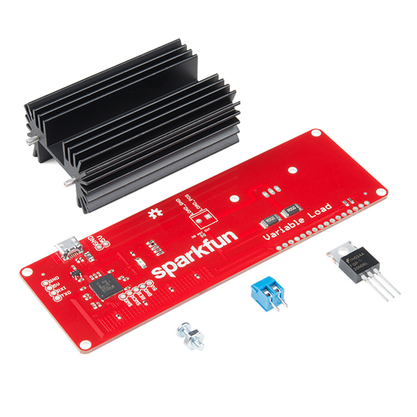
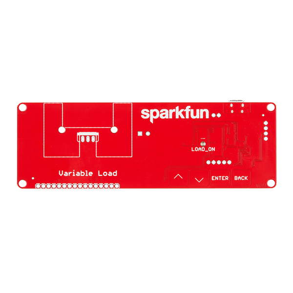
The SparkFun Variable Load Kit is a quick-to-assemble board designed to allow users to draw a specific amount of current from a voltage input. This kit can be used to test stability of the power supply under various loads, battery lifetime, safety cutoffs and other design elements. The Variable Load Kit can test supplies of up to 30V at currents ranging from a few mA all the way up to 4A.
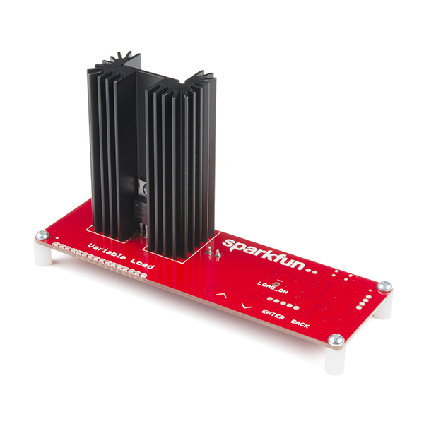
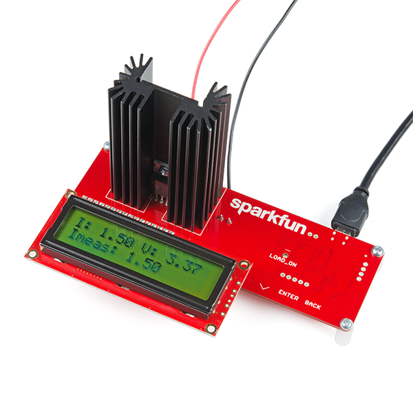
The Variable Load board is meant to work with one of two output modes: either using a console on a PC for feedback or using a 16x2 character LCD (found in the Hookup Accessories section below). In either case, the capacitive touch buttons on the front of the Variable Load PCB can be used to change the settings. There are four buttons: up arrow, down arrow, enter and back. The up and down arrow keys will adjust the current set point, the enter key turns the load on or off, and the back button resets the set point to zero. Additionally, there is an LED visible that will tell you whether the load is enabled or disabled at any given time.
For safety, please be sure that the total load power is limited to 15W because, even at that wattage, the heatsink will get hot to the touch.
Note: This kit will need to be assembled before use, so knowledge of soldering will be required. Also, the SparkFun Variable Load Kit does NOT include headers or an LCD to solder them to.
- 1x Variable Load Board
- 1x N-Channel MOSFET 60V 30A
- 1x Multiwatt Package Large Heatsink
- 1x Screw Terminal (2-Pin)
- 1x Hex Nut (4-40)
- 1x Phillips Head Screw (4-40, 3/8")
- 4x Phillips Head Screw (4-40, 1/4")
- 4x Plastic Standoff (4-40; 3/8")
SparkFun Variable Load Kit Product Help and Resources
Variable Load Hookup Guide - Revised
May 25, 2018
This tutorial will show you how to assemble and use SparkFun's Variable Load board. It can be used to test stability of the power supply under various loads, battery lifetime, safety cutoffs, and other design elements of power supplies under test.
Core Skill: Soldering
This skill defines how difficult the soldering is on a particular product. It might be a couple simple solder joints, or require special reflow tools.
Skill Level: Rookie - The number of pins increases, and you will have to determine polarity of components and some of the components might be a bit trickier or close together. You might need solder wick or flux.
See all skill levels
Core Skill: DIY
Whether it's for assembling a kit, hacking an enclosure, or creating your own parts; the DIY skill is all about knowing how to use tools and the techniques associated with them.
Skill Level: Noob - Basic assembly is required. You may need to provide your own basic tools like a screwdriver, hammer or scissors. Power tools or custom parts are not required. Instructions will be included and easy to follow. Sewing may be required, but only with included patterns.
See all skill levels
Core Skill: Programming
If a board needs code or communicates somehow, you're going to need to know how to program or interface with it. The programming skill is all about communication and code.
Skill Level: Rookie - You will need a better fundamental understand of what code is, and how it works. You will be using beginner-level software and development tools like Arduino. You will be dealing directly with code, but numerous examples and libraries are available. Sensors or shields will communicate with serial or TTL.
See all skill levels
Core Skill: Electrical Prototyping
If it requires power, you need to know how much, what all the pins do, and how to hook it up. You may need to reference datasheets, schematics, and know the ins and outs of electronics.
Skill Level: Competent - You will be required to reference a datasheet or schematic to know how to use a component. Your knowledge of a datasheet will only require basic features like power requirements, pinouts, or communications type. Also, you may need a power supply that?s greater than 12V or more than 1A worth of current.
See all skill levels
Comments
Looking for answers to technical questions?
We welcome your comments and suggestions below. However, if you are looking for solutions to technical questions please see our Technical Assistance page.
Customer Reviews
4 out of 5
Based on 1 ratings:
5 of 6 found this helpful:
Useful product with several rough edges
The SparkFun Variable Load works as described, and is a useful addition to my toolkit.
There are a number of small things wrong with it, some of which have been pointed out before in the comments:
If assembled as instructed, the LCD will get in the way of the buttons a bit. I elected to avoid this problem by soldering male right-angle header onto the LCD, and female right-angle header onto the variable load board. Then I can mate them, and the two boards are at the same level, with the LCD in front, not obscuring anything. I used M2.5 screws and standoffs to make "feet" for both the LCD and the variable load board.
The firmware updates the LCD much faster than the LCD can handle, so the lower-order digits are illegible. (And this is especially a problem if it's hovering right around 4.99-5.00 volts, for example, because then all the digits are illegible.)
The capacitive touch buttons seem designed for tiny fingers. My fat fingers often hit two buttons at once. It would be nice if the buttons were bigger, or even better would be to use tactile buttons instead of capacitive.
It would have been nice if this product had been based around an AVR or some other microcontroller more commonly used in the maker/open-source community. I would like to hack on the firmware, but I would have to get used to a new toolchain, and purchase a new programmer, which I don't feel is worth the effort and expense.
It's a little disappointing that with the display installed, the left-most cap-touch button is hiding under the display. Though, this could probably be worked around by either using a ribbon cable to connect the display, or right-angle header on the variable load board, and right-angle pins on the display.
TBH I didn't notice this during testing because I used a right angle header to connect my LCDs. It keeps the profile of the whole thing lower.
In case you don't have an LCD and don't want to use the console, I created a GUI for Windows and macOS. You can give a try here : https://github.com/casiez/SparkfunVariableLoadGUI
That is pretty cool. Up-voted!
Is there a way to enter a selection through the console? It seems that you still have to press the enter button manually. I'm trying to control this programmatically through a raspberry pi so that it can set a certain load based on other analog inputs to the pi, but I'm having a lot of difficulty. Has anyone had any success with similar tasks? Any thoughts on whether it would be best to try to emulate keyboard and cursor events in python or just try to read and understand the serial data being sent and copy that to some of the serial ports available on the VL? As for the enter button, I'm starting to think I may literallly have to connect a servo with a stylus to push it...
Alternatively, has anyone heard of any other similar products that might work instead? I haven't seen anything that does what this does! It seems like a really cool idea, but maybe some of the important features are just still under development.
Apparently I can't review a product I bought from a reseller, but if I could I'd give this thing zero stars
The firmware is insanely buggy, the serial control is just a hacky afterthought which blocks on write when it's opened resulting in the load actually slowing down if your reading device doesn't read the buffer fast enough.
The PID controller is just bad full stop and bugs out when you're on a current limiting supply. How are people to use this for testing their current limited supplies then?
Sparkfun just go "oh but it's opensource" - well great job choosing a PSoC that requires a special flashing tool because apparently they can't be bothered to include a programmer on board, so it's possibly the least accessible hardware ever.
The load can only be enabled and disabled via the touch sense button on the PCB. Apparently adding the 2 lines of C code to do that via the Serial port was just not something they thought of.
And after they started dumping these terrible things on the market here they have not responded to a single issue on their Github page.
Do not buy this thing. Just don't. Which is an awful shame because if they'd just let anyone other than a rank amateur QA this thing and make some small fixes they could have had a very useful product, but until my $100 Cypress programming cable arrives it might as well be a paper weight for me.
In another comment below, it was mentioned that there exists a $10 programmer. (Haven't tried it myself, though.)
I'm looking at modify the FW and noticed some files (project.h) are missing from the git repo. Anyone know how to track them down?
I haven't actually started using this to test anything yet but, upon building it, I've immediately made some mods.
Hopefully this may help someone else. Cheers.
From the perspective of an experienced software engineer getting into hardware, this is a decent kit.
Compared to no-name testers from Amazon or AliExpress, this is a better build. It's simpler, interfaceable and less busy.
It's also failsafe. You won't blow anything up.
If you get some 2mm jumper pins, you can easily wire a 1602 display at a 30 degree angle so that the front rests on the table next to it and doesn't block the capacitive buttons. The backlight for the display is not wired by default so you'll have to hook up those pins to the USB power (there are solder points available).
I opted for putting the screw terminals on top.
The hunky heat sink doesn't really solder well on the board (the pad outlines are too tiny) but a nice big ball of solder at least keeps it from falling out.
If you want a reliable kit for a reasonable price, this is the thing, though I really recommend SparkFun update the design by somebody who has any sense of aesthetic.
I have the pre May 2018 version. I updated the firmware to the current release via a MiniProg3 programmer and SWD. The system updated without issue. I now have a working and updated load tester! And can now update the firmware via the usb. Considering adding a few features when time permits!
Hi, I'd love to hear more about how you did this--how do you access the new firmware and how exactly did you upload it to the board etc? I have two and I'd love to be able to update them, but I don't think I'm quite as savvy as you are!
Any Update on why Vref seems to change based upon input voltage?
Input voltage as in, supply voltage or load voltage? The Vref for the part is in fact supply voltage / 2, which accounts for that. This is an internal limitation of the part used. It does have a stable 1.024V internal reference but that can't be used with the full range of ADC.
Per your previous post, we discussed that the Voltage on the display was not accurate. You said you were surprised and would look into this. Please review the posts. Seems that an inexpensive Voltage Reference Zener Diode would have solved this problem?
From the schematic, it looks like the Variable Load Kit does not supply power to the LCD backlight. Does this make the LCD hard to read?
IME it depends on the LCD you use. If you use a standard black-on-green LCD, the answer is no. However, some of the more unusual combinations we sell may be a little hard to read. I'd stick with a standard LCD for best results.
I purchased two units and they basically work, but the voltage readout on both units is about 200 mV low on a 3.3V input. Also, the update rate is too fast on both the LCD display and USB port. The lowest digit on the LCD toggles so fast that it is not readable. What is needed is an averaging/smoothing routine to sample a number of readings and then output the average values to the LCD and USB port.
What's your current draw, and what kind of wire are you passing the current through to the load? That may be the source of that voltage drop...I know when I tested some higher currents, I had issues with voltage drop across the wire.
As for the averaging, we'll consider adding that in the next revision.
I measured the voltage right at the unit to confirm that it wasn't due to ohmic drop. Also, with the unit drawing zero amps, the voltage reading on BOTH units is about 200 mV low. Drawing 2A, the display still reads 200 mV low as compared to the voltage right at the input connector. What is the tolerance of the resistors in the voltage divider?
They're 1% resistors so 200mV is WAY out of spec for those.
Is that 200mV consistent across load voltages?
Applied 19.2V, reads 18.2x at I=0.00A Applied 9.2V reads 8.7xx (where xx is fluctuating) Applied 5.0V reads 4.6xx Applied 3.3V reads 3.0xx - 3.1xx Current measurement looks very good though.
That's very strange. I have a production sample on my desk and I'm applying 3.75V and it's reading 3.70V. Even at 16.8V it reads pretty true at 16.7V. I'm not sure what to make of this.
I'm wondering if anyone else has seen this behavior?
Please make sure someone didn't substitute in 5% resistors. If you can point out the voltage divider on the board, I can make additional readings.
Next to the LED there's a stack of five resistors. The top three comprise the voltage divider (I combined a 787 and 8.2k to get closer to 9k for a 10:1 ratio).
Voltage divider is within 1%. Applied 3.30V, divider tap reads 0.332V (0.6% error), display shows 3.12V.
Fascinating. Can you verify that the board is getting a good 5v supply?
Good Call! My USB Hub was putting out 5.30V. When I moved it to my laptop, Vusb=5.05V and the display values are much closer to reality. Vin 3.3 reads 3.26, Vin 5.0 reads 4.95, Vin 19.2 reads 19.1. Current draw has no effect on reading. Obviously, the Vref is affected by Vdd.
That's very interesting. Vref uses an internal reference for the ADC, so I'd expect that to not affect the readings that much.
I'll do a little more research so I understand that better. I'm glad we solved your issue!
Also, adding a 22 uF cap on the 5V rail on the board significantly reduces the jitter in the voltage reading.
Under windows 7, and because of the custom USB VID and PID, a custom .inf file is required to load the standard usbser.sys
I've added a custom INF file to the repository. Go ahead and give it a try. I tried it on the one Windows 7 machine I could find and it worked.
Does it use a 8 bit DAC or a 16 bit PWM to set the load current?
It uses two 8-bit DACs, one for a coarse adjust and one for a fine adjust.
Does it use both DACs at the same time? Are the two outputs summed together using series resistors? What are the ranges of the coarse and fine DAC? Could you say current set resolution is 8bit+8bit=16bit?
I don't think you can truly say that it's 16-bit. It uses both at once, summed together. One of them is a 0-4.096V, the other is 0-1.024V.
Sometimes ya just gotta take a load off
Is there a way to alter the wattage to drive higher after upgrading the heatsink? I'd like to test my 14v 4a power supply, which would be closer to 56w
The firmware is, of course, open source, but it's written in C and developed under the PSoC Creator IDE from Cypress.The actual safety cut-out is pretty simple, just taking the current set point and multiplying it by the source voltage and shutting the circuit down if the product is greater than 15W. Changing it would be one line of code. More challenging is that you'd need a programmer. The cheapest option for a programmer is to get the CY8CKIT-059 dev kit and snap off the programmer.
Hello, I have the older version of the load kit pre-2018 May update. Can you please help me update the firmware using the CY8CKIT-059 dev kit as you mentioned. I bought the programmer kit recently bit I,m not sure how to use it.
This is quite disappointing, because the firmware seems like quite a rush job. Some big oversights like not being able to enable the load over serial and then you have to get a programmer to flash it - not so easy to order in some parts of the world...
The quickie hack could play with the shunt resistor and feedback resistor values. But you would have to mentally scale the display.
Read the data sheet for the MOSFET to determine SOA for DC; and calculate Tj for your particular VA.
Things that can be done to enable increased load power - use a bergquist (SP900 or similar) 'thermal transfer' insulator pad in lieu of the heatsink goop. - airflow directly on the heatsink (at least 15 CFM) - CV vs CC modes (depends on the compliance V)
Is this only for DC loads or what frequency range does this support?
Per the schematic, DC only.