- Home
- Product Categories
- Connector Boards
- SparkFun Qwiic Adapter

SparkFun Qwiic Adapter
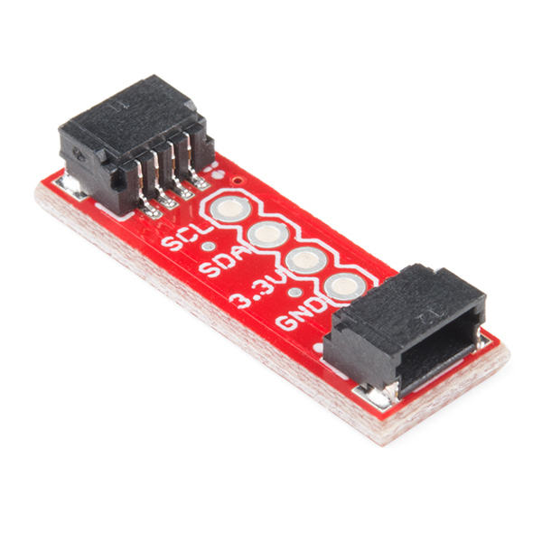
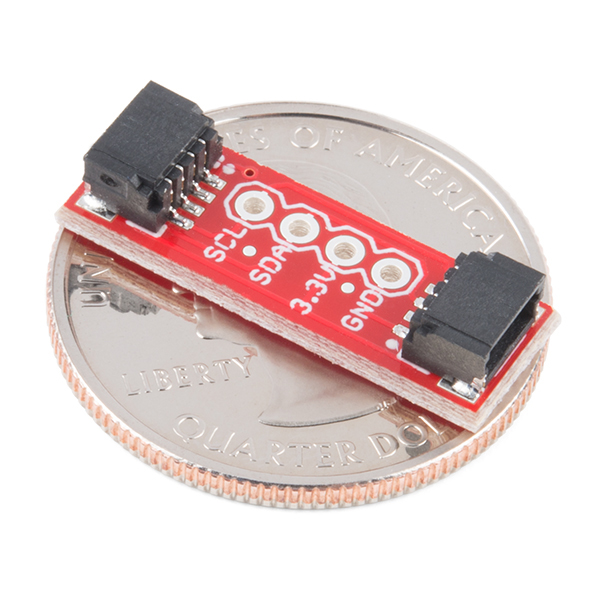
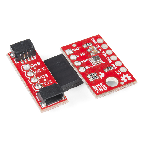
The SparkFun Qwiic Adapter provides the perfect means to make any old I2C board into a Qwiic-enabled board. This adapter breaks out the I2C pins from the Qwiic connectors to pins that you can easily solder with your favorite I2C-enabled device.
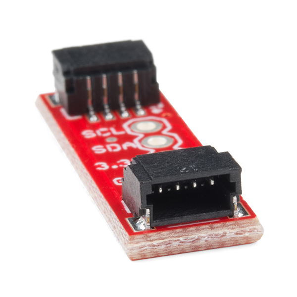
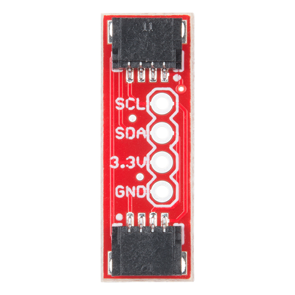
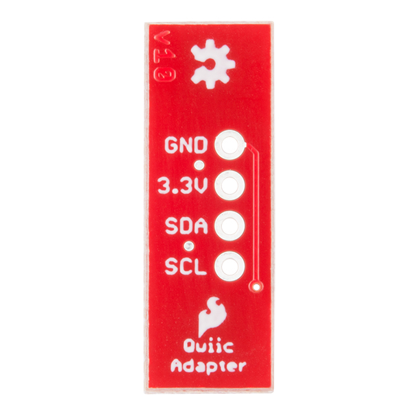
The Qwiic Adapter has two Qwiic connection ports, all on the same I2C bus. Four plated through holes are broken out for SCL, SDA, 3.3V and GND. These pins can be used to convert an old I2C-enabled device into a Qwiic-enabled board.
The SparkFun Qwiic Connect System is an ecosystem of I2C sensors, actuators, shields and cables that make prototyping faster and less prone to error. All Qwiic-enabled boards use a common 1mm pitch, 4-pin JST connector. This reduces the amount of required PCB space, and polarized connections mean you can’t hook it up wrong.
- 2x Qwiic Connection Ports
- Broken-out I2C Pins
SparkFun Qwiic Adapter Product Help and Resources
Qwiic Adapter Hookup Guide
November 30, 2017
Get started with your Qwiic adapter board. This adapter breaks out the I2C pins from the Qwiic connectors to pins that you can easily solder with your favorite I2C enabled device.
GPS-RTK Hookup Guide
September 13, 2018
Find out where you are! Use this easy hook-up guide to get up and running with the SparkFun high precision GPS-RTK NEO-M8P-2 breakout board.
GPS-RTK2 Hookup Guide
January 14, 2019
Get precision down to the diameter of a dime with the new ZED-F9P from u-blox.
Core Skill: Soldering
This skill defines how difficult the soldering is on a particular product. It might be a couple simple solder joints, or require special reflow tools.
Skill Level: Noob - Some basic soldering is required, but it is limited to a just a few pins, basic through-hole soldering, and couple (if any) polarized components. A basic soldering iron is all you should need.
See all skill levels
Comments
Looking for answers to technical questions?
We welcome your comments and suggestions below. However, if you are looking for solutions to technical questions please see our Technical Assistance page.
Customer Reviews
5 out of 5
Based on 3 ratings:
Love these little guys.
The easiest way to add Qwiic connectors to a project.
Does this have an integrated resistor for pull-up?
Hi!
Sorry, I just saw your question. If your question has not been answered yet...
Unfortunately, no. As the product description states, it has "four plated through holes [that] are broken out for SCL, SDA, 3.3V and GND". This also includes two Qwiic connectors. This is to convert boards that do not have the Qwiic connectors built in. SparkFun breakout boards usually have built-in pull-up resistors so we do not include it on the board. This also reduces the cost of the board.
You could manually solder two through hole resistors using the plated through holes (probably 2.2kΩ resistors but it depends on your device and system) if you really need.
Sometimes, you've just gotta make do with what's handy...
I needed to connect the DMM to a couple of points on my breadboard, but not enough hands to juggle the probes and the rest of the stuff...
It finally dawned on me that I happen to have one of these Qwiic Adapters, a Qwiic Cable - Breadboard Jumper (OK, I'll admit that what actually came to hand was the Adafruit equivalent) and an Adafruit Qwiic cable with alligator clips (hmm... conspicuous by it's absence from the SparkFun storefront...)
Anyway, by hooking these three together (I hadn't gotten around to soldering pins into the Qwiic Adapter, so had to use it as-is), and I suddenly had four breadboard to alligator clip jumpers, two of which connected to the DMM! I don't think this was what Nate & company had in mind when they first came up with the Qwiic system, but it did what I needed!
I would like to suggest a version 2 of this adapter. Qwiic adapter system is an excellent way to connect sensors. However, there are many sensors/display out there where the i2c pins do not line up exactly correct. Either the vcc/gnd or the sclk/sda are reversed (maybe both). While I consider my soldering skills as excellent the design of this makes it extremely difficult to manage reconfiguring the pinouts. I would like to see one that would truely allow adapting to various i2c designs. A simple cut an etch (standard config) and solder pads would be acceptable.
I believe the original was intended for users to add wires between the boards and not match the layout of other boards. Another option is to use one of the Qwiic cables and solder the ends to the other sensor.
The color coding is:
I'm new to Arduino so this could be a dumb question, but is there something special about I2C sensors? I was given a large collection of very old Arduino stuff including all sorts of sensors, but none of them have qwiic connectors. If I take a random sensor and make the appropriate connections to this adapter, will my sensor work if I connect it to a RedBoard using the qwiic connector? Or, does the sensor need to be I2C compatible somehow?
Hi there, it sounds like you are looking for technical assistance. Please use the link in the banner above, to get started with posting a topic in our forums. Our technical support team will do their best to assist you.
That being said, I2C is a communication protocol. Your sensor would already have to be I2C compatible. Additionally, the Qwiic connection system is for ease of prototyping; to solve the old issue of having to solder and wire things up correctly. Our Qwiic devices have the necessary I2C connections wired so that users only need the cables to attach a Qwiic device. (Hence, Qwiic is a play on words between quick and I2C.)
...seems like everytime i go to develop something the pins are sooo close, but never in the right order.
I was develping a kit using a Fio v3 with an adafruit ads1115, to build to a breadboard only to find the SDA and SCL plins were swapped...after i had assembled, production pcb boards made.
I wanted to use this breakout to take the revised board(now using Fio V3 pin layout) to connect to an alternative Qwiic based board...in relation to the Fio v3 layout the board is based on....the 3.3 and GND plins are swapped...BAHHH!!!
I'm not quite sure what you are saying, but if you need assistance please head over to our forums and create a new topic (there is an additional link at the top of the comment section, above the comment submission section).
Update: It sounds like you might have been trying to solder this breakout directly to the Fio v3. If you need help with the pin layout of the Fio, there is a great picture in the hookup guide. Also, this board is only mean to break out the pins of the Qwiic connectors; the ordering of the pins only reflects the order of the pins on the Qwiic connectors.
Please consider making a version of this board with built-in level shifting. No need for a boost convertor; the 5v side can be powered by the project it is plugged into. Just start with this board, add the standard MSOFETs & pull-ups, and add the three pins for 5v0 (in), SDA5 and SCL5 (don't get rid of the 3v3 power & signal pins though).
Can these be used to simply extend a connection between a board and a sensor/device?
In other words, could I setup something like this?: Photon on Qwiic Shield --> Qwiic Cable - 100mm --> Qwiic Adapter --> Qwiic Cable - 100mm --> Qwiic sensor of some sort
Thanks!
Yes, this can be used as a coupler to join two cables. However, longer cable runs might be less reliable. This page provides some guidelines , but it mentions 4 ft as a practical upper limit for Qwiic.