- Home
- Product Categories
- Monochrome
- SparkFun Micro OLED Breakout (Qwiic)

SparkFun Micro OLED Breakout (Qwiic)
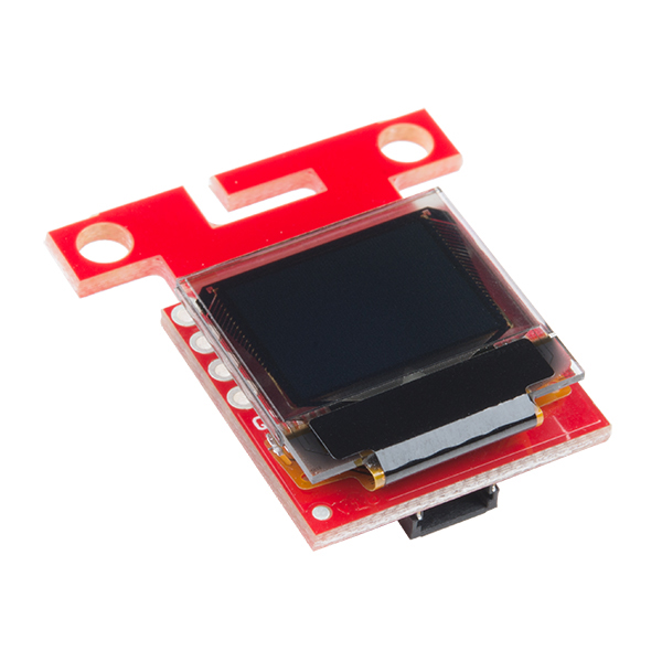
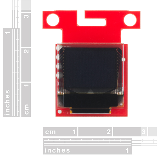
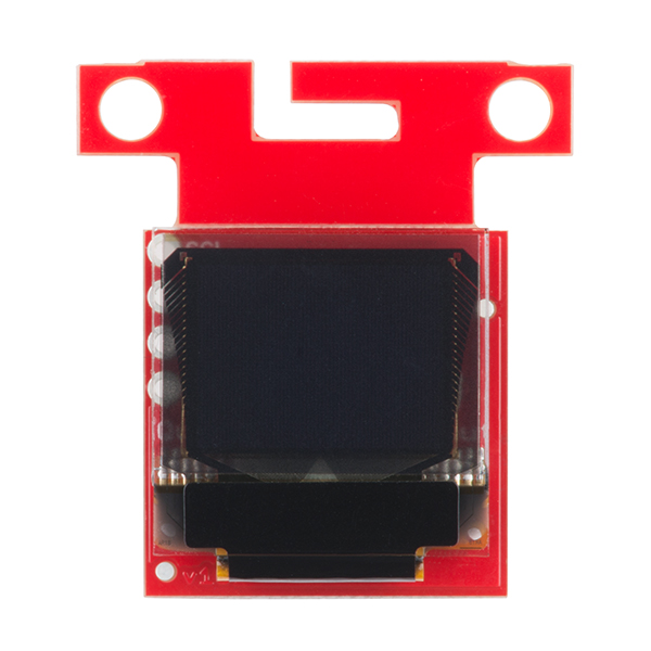
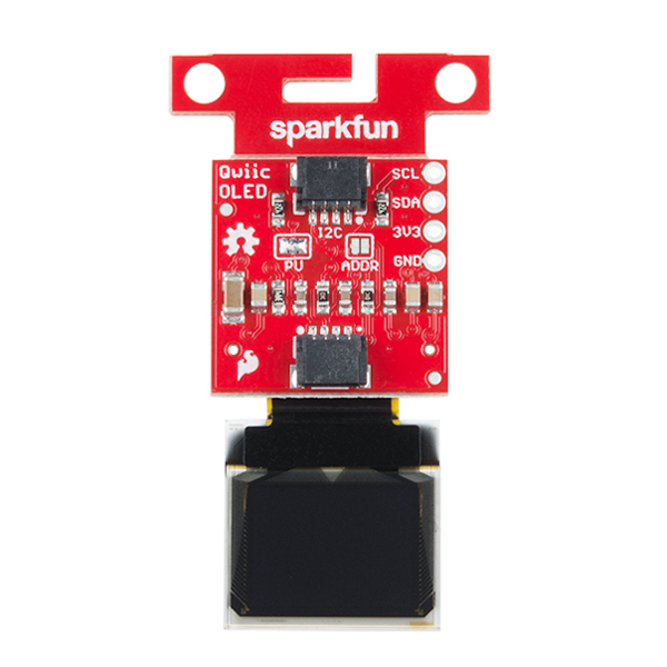
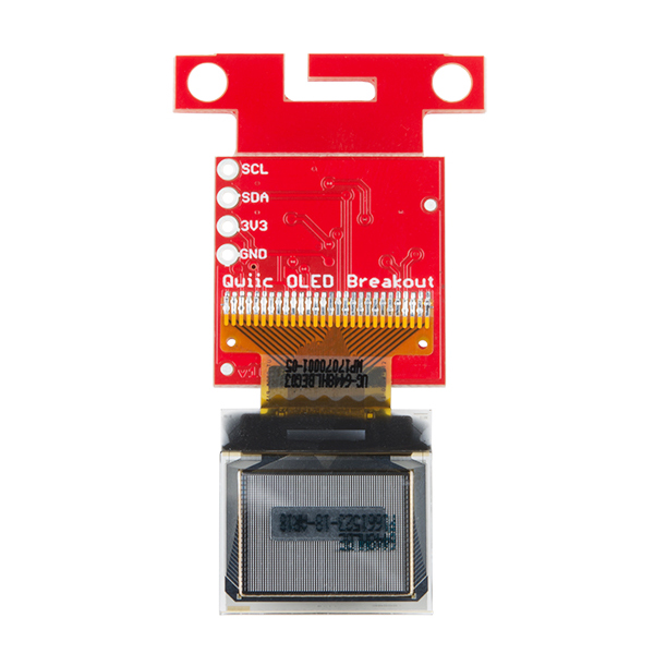
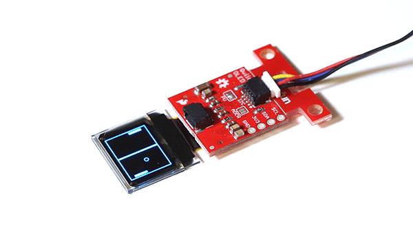
The SparkFun Qwiic Micro OLED Breakout is a Qwiic-enabled version of our popular Micro OLED display! The small monochrome, blue-on-black OLED screen presents incredibly clear images for your viewing pleasure. It’s “micro,” but it still packs a punch --- the OLED display is crisp, and you can fit a deceivingly large amount of graphics on there. This breakout is perfect for adding graphics to your next project and displaying diagnostic information without resorting to a serial output, all with the ease of use of our own Qwiic Connect System!
This version of the Micro OLED Breakout is exactly the size of its non-Qwiic sibling, featuring a screen that is 64 pixels wide and 48 pixels tall and measuring 0.66" across. But it has also been equipped with two Qwiic connectors, making it ideal for I2C operations. We've also added two mounting holes and a convenient Qwiic cable holder incorporated into a detachable tab on the board that can be easily removed thanks to a v-scored edge. We've even made sure to include an I2C pull-up jumper and ADDR jumper on the back of the board, so if you have your own I2C pull-ups or need to change the I2C address of the board, you have options!
Note: The I2C address of the Micro OLED is 0x3D and is jumper selectable to 0x3C. A multiplexer/Mux is required to communicate to multiple Micro OLED sensors on a single bus. If you need to use more than one Micro OLED sensor consider using the Qwiic Mux Breakout.
The SparkFun Qwiic Connect System is an ecosystem of I2C sensors, actuators, shields and cables that make prototyping faster and less prone to error. All Qwiic-enabled boards use a common 1mm pitch, 4-pin JST connector. This reduces the amount of required PCB space, and polarized connections mean you can’t hook it up wrong.
- Qwiic-Connector Enabled
- Operating Voltage: 3.3V
- Operating Current: 10mA (20mA max)
- Screen Size: 64x48 pixels (0.66" Across)
- Monochrome Blue-on-Black
- I2C Interface
SparkFun Micro OLED Breakout (Qwiic) Product Help and Resources
Assembly Guide for SparkFun JetBot AI Kit
August 13, 2019
Assembly Guide for the SparkFun JetBot AI Kit. This tutorial includes photos & comments to assemble the two-layer chassis & additional components unique to the JetBot kit.
Qwiic Digital Indoor Thermometer
July 15, 2020
Qwiic-ly build a digital indoor thermometer to measure the ambient temperature of the room and display it using an OLED on an I2C bus!
Qwiic Micro OLED Hookup Guide
January 18, 2018
Get started displaying things with the Qwiic Micro OLED.
Displaying Your Coordinates with a GPS Module
April 30, 2019
This Arduino tutorial will teach you how to pinpoint and display your GPS coordinates with a press of a button using hardware from our Qwiic Connect System (I2C).
Assembly Guide for SparkFun JetBot AI Kit V2.0
March 27, 2020
Assembly Guide for the SparkFun JetBot AI Kit v2.0. This tutorial includes photos & comments to assemble the two-layer chassis & additional components unique to the JetBot kit.
Everything You Should Know About HyperDisplay
February 20, 2019
This is a tutorial to go in-depth about the SparkFun HyperDisplay Arduino Library.
GPS Geo-Mapping at the Push of a Button
September 27, 2019
Let's ramp up our GPS tracking skills with KML files and Google Earth. We'll make a tracker that logs location and allows us to visualize our steps with Google Earth.
Qwiic GPS Clock
September 14, 2020
What time is it? Time for you to... Qwiic-ly build a GPS clock and output it to a display! This project provides you with the current date and time using GPS satellites. Read the date and time as a digital or analog clock. Or even configure the clock for military, your time zone, or automatically adjust the time for daylight savings time!
MicroMod Qwiic Pro Kit Project Guide
September 29, 2022
The MicroMod Qwiic Pro Kit was designed to allow users to get started with Arduino without the need for soldering or a breadboard. We've included three inputs (a joystick, accelerometer, and proximity sensor) and one display that can be daisy chained to the MicroMod SAMD51 Processor Board.
Qwiic Pro Kit Project Guide
November 7, 2019
The Qwiic Pro Kit was designed to allow users to get started with Arduino without the need for soldering or a breadboard. We've included three inputs (a joystick, accelerometer, and proximity sensor) and one display that can be daisy chained to the RedBoard Turbo (SAMD21) Development Board.
Qwiic Kit for Raspberry Pi V2 Hookup Guide
December 29, 2022
Get started with the SGP40, BME280, VCNL4040, and microOLED via I2C using the Qwiic system and Python on a Raspberry Pi! Measure VOC Index, light, temperature, humidity, and pressure from the environment. Then display them on the microOLED, serial terminal, or the cloud with Cayenne!
LiPo Fuel Gauge (MAX1704X) Hookup Guide
February 23, 2023
Monitor your LiPo battery with the LiPo fuel gauge! In this tutorial, we will be using the MAX17043 and MAX17048 to monitor a single cell, LiPo battery over the Arduino Serial Monitor. We will also connect a display to view the output without the need to connect the microcontroller to a computer.
AzureWave Thing Plus (AW-CU488) Hookup Guide
September 22, 2022
The SparkFun AzureWave Thing Plus is a Feather form-factor development board equipped with the AW-CU488. We'll highlight key features of the board and show you to get started with the development board. A few Arduino examples will be highlighted to connect to a WiFi router, calculate the Fast Fourier Transform (FFT) from an input microphone, output an analog signal to a speaker, and connect an Qwiic-enabled device.
Core Skill: Programming
If a board needs code or communicates somehow, you're going to need to know how to program or interface with it. The programming skill is all about communication and code.
Skill Level: Competent - The toolchain for programming is a bit more complex and will examples may not be explicitly provided for you. You will be required to have a fundamental knowledge of programming and be required to provide your own code. You may need to modify existing libraries or code to work with your specific hardware. Sensor and hardware interfaces will be SPI or I2C.
See all skill levels
Core Skill: Electrical Prototyping
If it requires power, you need to know how much, what all the pins do, and how to hook it up. You may need to reference datasheets, schematics, and know the ins and outs of electronics.
Skill Level: Rookie - You may be required to know a bit more about the component, such as orientation, or how to hook it up, in addition to power requirements. You will need to understand polarized components.
See all skill levels
Comments
Looking for answers to technical questions?
We welcome your comments and suggestions below. However, if you are looking for solutions to technical questions please see our Technical Assistance page.
Customer Reviews
3.6 out of 5
Based on 7 ratings:
1 of 1 found this helpful:
Great little display
The hookup guide and python library samples were a big help getting this display integrated into my project.
2 of 2 found this helpful:
Does not work with Artemis Nano
This does not work with Artemis Nano. Works on a Pi though. Need to add void MicroOLED::i2cSetup() { Wire.begin(); } in hardware.cpp file
Sorry you're having trouble! It looks like the "MicroOLED_Demo_I2C" example code for this doesn't quite work with the Artemis without a slight modification to the code but the "MicroOLED_Rick_and_Morty_I2C" sketch works when I try it here. (The Demo sketch needs different analog pins defined.)
Artemis is still in it's infancy and we're in the process of updating libraries and example code on Qwiic products that were designed before Artemis existed. Eventually everything should be covered but for now some Qwiic products require a bit of tweaking to get working.
If you run into questions about a product running on Artemis, post that in our Artemis forum and our techs will have a look.
2 of 2 found this helpful:
Small but bright!
I knew when I read 0.66" this screen would be tiny, but holy crap it was even smaller than I had thought. Thankfully it's clear, crisp, and bright blue. It can light up my whole room at night.
1 of 1 found this helpful:
Great Product, Weak Documentation
This is a fantastic product. The Qwiic interface makes the hardware connection very simple. I’m amazed at its low cost. SparkFun has made the schematics and library source code completely open.
With the available schematics, after prototyping, integrating the display into your PWB, I expect, would be a snap.
The library provided for Arduino and the example sketches, similarly make integrating this device to your software a snap. It’s really easy. I probably got the example sketch running in just minutes. I was amazed at the simplicity. And that is the good news.
The bad news is the poor documentation. My end-device isn’t going to be an Arduino. It’s going to be a custom PWB and it will be using a PIC processor. Porting the Arduino libraries to MPLAB was a lot more challenging than I thought it should be. Fortunately I was able to back out their design from the library source code. I’m very glad they generously made that available, but the code is not well documented.
Again, overall, a fantastic product at a great price. But if you’re going a step beyond hobby projects, be aware the lack of documentation will add effort to your project.
Mine was DOA
After a LOT of fiddling about and some scoping and also then Salae analysis... I conclude mines deader than dead, never worked at all... A real pity as was my first Qwiic expedition and left me feeling like I was missing something... Luckily all the other Qwiic and numerous I2C devices I have been working well. It's in the garbage bin as we speak. Poor QA... I2C can be quirky... but as I know full well having used it for over 10 years it either works or plain does not! In this case it's the display vs driver chip which cheerfully ACKs... T
Sorry to hear that! We test these but sometimes a dud can get through or a part can get damaged in shipment. Please contact our customer service department and we will help you get this sorted out.
Handy little display
For my case this little display was just what I needed. Low cost and most of all Qwiic-enabled. The display is very readable. I'm now going to get another one as my project has one master and one remote. I have no problem recommending this product.
Great Display - Short life?
I got this up and working on my compass project, and it was beautiful. Even a non-programmer like me was able to hack it into a great little compass graphic. Went to transfer into my final assembly after a few hours of prototype operation and nothing. Confirmed the voltage input was right, so not sure where it went sideways. Plugged into my original assembly and nada. My advice, order two, in case one goes south.
Are there going to be guides to using the Qwiic devices on a Raspberry Pi, without using an Arduino?
Qwiic with raspberry pi tutorials can be found here: https://github.com/sparkfun/Qwiic_Py/tree/master/qwiic/drivers Just choose the folder for you Qwiic product. Hope that helps
We currently are not planning on adding Raspberry Pi to these tutorials.
So why create the SparkFun Qwiic HAT for Raspberry Pi? Sales Ploy?
Please check out our new tutorials, in the Tutorials section above.
The last part of the description says "If you need to use more than one Micro OLED sensor consider using the Qwiic Mux Breakout." I would assume this should say "if you plan to use more then 2 displays"? I would like to have 2 displays, addressed as 0x3C and 0x3D. I assume this will work without a mux, is this correct?
Please make a 128x64 version.
I added a note to the GitHub repository to see if we can look into it a new version.