- Home
- Product Categories
- IMU
- SparkFun VR IMU Breakout - BNO080 (Qwiic)

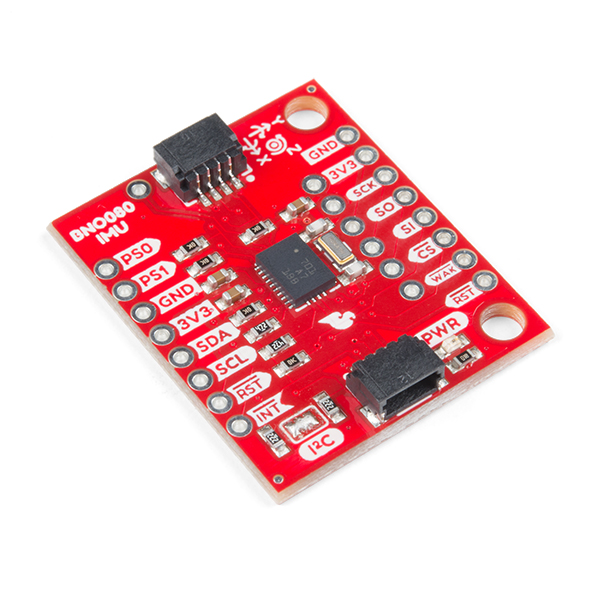
SparkFun VR IMU Breakout - BNO080 (Qwiic)
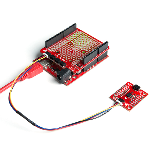
Virtual reality is in, but you shouldn't have to drop hundreds of dollars to gain access to the technology behind it. Luckily, that's where the SparkFun VR IMU Breakout comes in. At its heart is Bosch’s BNO080, a combination triple-axis accelerometer/gyro/magnetometer SiP, packaged with a 32-bit ARM Cortex M0+. The BNO080 Inertial Measurement Unit (IMU) produces accurate rotation vector headings, excellently suited for VR and other heading applications, with a static rotation error of two degrees or less. The VR IMU is exactly what we’ve been waiting for: All the sensor data is combined and drift-corrected into meaningful, accurate IMU information. It’s perfect for any project that needs to sense orientation or motion. This IMU breakout board has also been equipped with two I2C Qwiic connectors, in order to make interfacing with the tiny, QFN package a bit easier. It’s part of SparkFun’s Qwiic connect system, so you won’t have to do any soldering to figure out how things are oriented. However, we still have broken out 0.1"-spaced pins in case you prefer to use a breadboard.
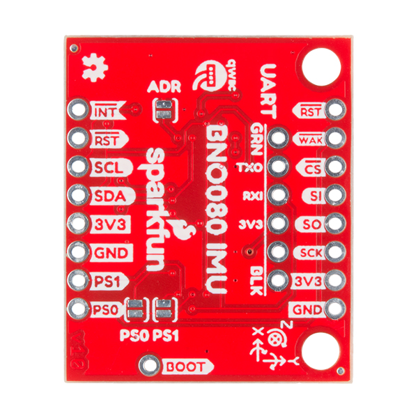
The BNO080 was designed to be implemented in Android-based cellular phones to handle all the computations necessary for virtual reality goggles using only your phone. The sensor is quite powerful, and with power comes a complex interface. Thanks to the solder jumpers on the board, you will be able to select between two different I2C addresses, but if I2C is not your first communication choice, the sensor is capable of communicating over SPI and UART as well! We’ve also written an I2C-based library that provides the rotation vector (the reading most folks want from an IMU) as well as acceleration, gyro and magnetometer readings, step counting, activity classifier (such as riding a bike) and calibration.
Note: The I2C address of the BNO080 is 0x4B and is jumper selectable to 0x4A. A multiplexer/Mux is required to communicate with more than two BNO080 sensors on a single bus. If you need to use more than two BNO080 sensors consider using the Qwiic Mux Breakout.
The SparkFun Qwiic connect system is an ecosystem of I2C sensors, actuators, shields and cables that make prototyping faster and less prone to error. All Qwiic-enabled boards use a common 1mm pitch, 4-pin JST connector. This reduces the amount of required PCB space, and polarized connections mean you can’t hook it up wrong.
Need a custom board? This component can be found in SparkFun's À La Carte board builder. You can have a custom design fabricated with this component - and your choice of hundreds of other sensors, actuators and wireless devices - delivered to you in just a few weeks.

- Operating Voltage: 1.65V - 3.6V
- I2C (Default): Up to 400kHz
- SPI: Up to 3MHz
- UART: 3Mbps
- Rotation Vector
- Dynamic Error: 3.5°
- Static Error: 2.0°
- Gaming Rotation Vector
- Dynamic Error: 2.5°
- Static Error: 1.5°
- Heading Drift: 0.5° / min
- Geomagnetic Rotation Vector
- Dynamic Rotation Error: 4.5°
- Static Rotation Error: 3.0°
- Gravity Angle Error: 1.5°
- Linear Acceleration Accuracy: 0.35m/s2
- Accelerometer Accuracy: 0.3m/s2
- Gyroscope Accuracy: 3.1° / sec
- Magnetometer Accuracy: 1.4µT
- 2x Qwiic Connection Ports
SparkFun VR IMU Breakout - BNO080 (Qwiic) Product Help and Resources
Qwiic VR IMU (BNO080) Hookup Guide
April 30, 2018
Figure out how things are oriented with the robust 9 degrees of freedom (DOF) BNO080 IMU. Maybe even make your own virtual reality (VR) applications if you're feeling savvy.
Core Skill: Programming
If a board needs code or communicates somehow, you're going to need to know how to program or interface with it. The programming skill is all about communication and code.
Skill Level: Competent - The toolchain for programming is a bit more complex and will examples may not be explicitly provided for you. You will be required to have a fundamental knowledge of programming and be required to provide your own code. You may need to modify existing libraries or code to work with your specific hardware. Sensor and hardware interfaces will be SPI or I2C.
See all skill levels
Core Skill: Electrical Prototyping
If it requires power, you need to know how much, what all the pins do, and how to hook it up. You may need to reference datasheets, schematics, and know the ins and outs of electronics.
Skill Level: Rookie - You may be required to know a bit more about the component, such as orientation, or how to hook it up, in addition to power requirements. You will need to understand polarized components.
See all skill levels
Comments
Looking for answers to technical questions?
We welcome your comments and suggestions below. However, if you are looking for solutions to technical questions please see our Technical Assistance page.
Customer Reviews
3 out of 5
Based on 5 ratings:
2 of 2 found this helpful:
Best MEMS gyro I've ever purchased (and I've bought most of 'em)!
IMHO, a gyro capable of keeping track of heading (i.e., integrating angular velocity) must have its own IMU for doing the calculations and filtering: this one has it! The Bosch BNO055 has one too but I found that gyro insensitive at low angular velocities. This one is very accurate with very little drift. This is the gyro that I've been waiting for (and have spent many $100s in my search).
1 of 1 found this helpful:
Works great
First use of qwiic and qwiic hat for raspberry pi. Very convenient.
The chipset is packed with features. Manufacturers docs are extensive. Was able to get a .net core/c# library up and going in short order.
1 of 1 found this helpful:
RPI Easy I2C Library
Great IMU, just started using it. Only thing is SparkFun, doesn't support a I2C Python library upfront. Didn't use it for over a year, using the ICM20949 instead and that worked great. Now knowing of a library that uses RPI/I2C/Qwiic connect, what can I say, I am so happy to use this VR level IMU.
You don't mention an RPI library, so you technically state there isn't an one for RPI you provide, so we should have taken that into account.
The link to the library: https://github.com/13221325403/BNO080IMU-pi
Has issues.
This IMU (2 boards tested) produces max of total range spikes on x,y,z at random intervals, both in-motion and not-in-motion (Using QWIIC and basic demo sketches provided)
It sounds like you may have received some damaged boards. Please contact our returns department by filling out the form on this page and we can get this fixed for you!
Not good...
I bought 2...haven't been able to get either one to work....
Please contact technical assistance for help. :-)
I have been using this board using a Qwiic cable to connect to a Sparkfun ESP32 WROOM Thing Plus. It generally goes well, however, on two occasions, a BNO080 board stopped being recognized (ie. in the Arduino library BNO080 the imu.begin() call returns false).
For example if I upload the following code to my ESP32 on line 46 the myIMU.begin() call returns false.
Like I said, it happened to me twice. I am merely using the ESP32 connected to the IMU board with a Qwiic cable. There is a LiPo battery connected to the ESP32. The IMU indicator power LED is on but I am unable to connect using i2c anymore. What could cause this and how can I fix it?
Hi there, it sounds like you are looking for technical assistance. Please use the link in the banner above, to get started with posting a topic in our forums. Our technical support team will do their best to assist you.
That being said, maybe it is a bad Qwiic cable. I have seen a few get broken from snags or users tugging on the wiring; instead of the connector (*I am often guilty of this "abuse").
Compiling the sketch in this thread gives me error:
exit status 1 'square' was not declared in this scope
Maybe I need another library for math installed ?
Hi there, it sounds like you are looking for technical assistance. Please use the link in the banner above, to get started with posting a topic in our forums. Our technical support team will do their best to assist you.
This chip and the supplied firmware does not provide the heading in degrees. It provides quarternion in radians.
There is a site which offers for sale a PIC18f4550 microcontroller firmware which provides the yaw in degrees, the pitch and roll in radian for the BNO080 at a king's ransom. But it works flawless!!
I believe little or no midification it can work with any PIC MCU. check out.. https://www.customtechnic.com/home/11-bno080-communication-with-pic-microcontrollers.html
I would like to use this board with a Raspberry Pi. Does it require the use I2C Clock Stretching (like the BNO050)? If so, does the Qwiic interface solve the Raspberry issue with clock stretching? If not, can I connect the BNO060 via UART still using the I2C connection/ cables?
I checked the datasheet for the BNO080, and it says the master "MUST" support clock stretching.
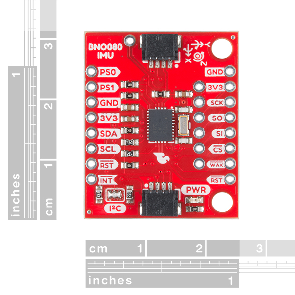
Does anyone know the dimensions of this board, and also the size & relative locations of the mounting holes? Thanks.
The board is 1.2"x1", the mounting holes are for a size 4 screw and are 1" apart, and .1" away from the each edge
How can the arduino library be used to get timestamps of the sensor readings?
The data packet contains a timestamp. I wish the code incorporated a way to get timestamps along with quaternions and the other kinematics.
Cool device!
If you want to use the Euler angles this is a good reference: https://www.vectornav.com/docs/default-source/documentation/vn-100-documentation/AN002.pdf
Or... struct Euler{ float yaw; float pitch; float roll; };
This isn't working. I have converted the code to Arduino and, if I rotate (yaw) the BNO080, then the both X and Y are thrown off and then settle back to 0.
I don't have the same issue. However, I am using the Spark X version with the Spark X Arduino UNO clone. When using Euler angles there is what is call a gimbal lock where a degree of freedom will be lost. I am simply using it for heading so Euler angles work well for me as it is laying flat in the horizontal. I have to first do a figure 8 with the board and then it points to North as zero. This sensor is really stable for me even when I have a strong magnet near it (which is a lot better than my phone compass). Here is my full set of code:
SWDUDE thank you so much. Your code is exactly what I was looking for and it works flawlessly. And many thanks to Sparkfun for wonderful module and fantastic library.
I would love to see a version of this with a corresponding bluetooth module for quick communication from a PC or mobile device!