- Home
- Product Categories
- Relay
- SparkFun Qwiic Single Relay

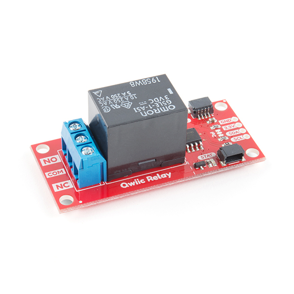
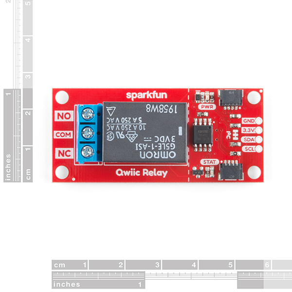
SparkFun Qwiic Single Relay
Have you ever wanted to control something powerful or have you ever needed to turn on/off a high power device from your Arduino or another low powered microcontroller? The SparkFun Qwiic Single Relay provides you with the easiest to use relay yet. The Single Relay board can handle up to 5.5A at 240VAC for long periods of time and allows you to control large power loads with simple I2C commands. Utilizing our handy Qwiic system, and on-board screw terminals, no soldering is required to connect it to the rest of your system!
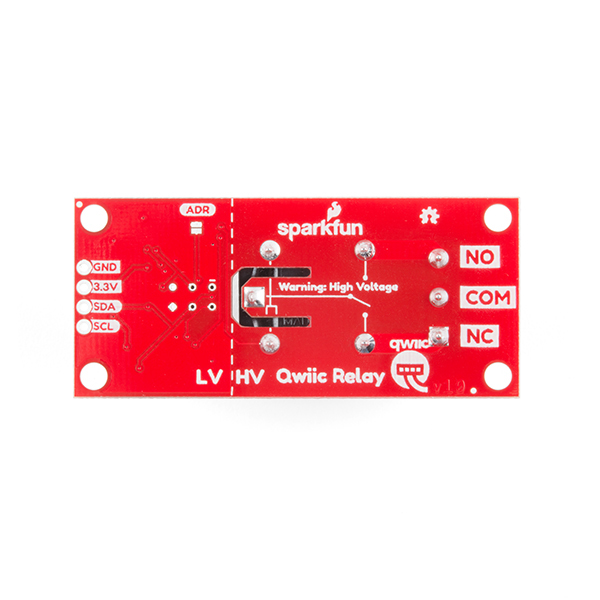
The Qwiic Relay comes with a default I2C address of 0x18 but can be changed with a simple command allowing you to control over 100 Qwiic Relays on a single bus (but please be aware that toggling lots of relays on a 3.3V bus can cause voltage spikes so an external power supply will be required)! In addition, there is an address jumper on the back of the board. Closing this jumper with solder will change the address to 0x19.
We've included many safety precautions onto the PCB including, ground isolation between the load and the low voltage control has been increased and an air-gap has been added around the common pin. The traces between the relay and the NC/NO/COM terminals have been doubled to increase the maximum current. But if you aren't comfortable playing with high voltage AC, that's understandable. Please consider using the IoT Power Relay, instead. It's not I2C supported but the IoT Power Relay contains shielding to prevent accidental shock and is great for learning how to use relay power accessories.
Note: The I2C address of the Single Relay is 0x18 and is jumper selectable to 0x19 (software-configurable to any address). A multiplexer/Mux is required to communicate to multiple Single Relay sensors on a single bus. If you need to use more than one Single Relay sensor consider using the Qwiic Mux Breakout.
The SparkFun Qwiic Connect System is an ecosystem of I2C sensors, actuators, shields and cables that make prototyping faster and less prone to error. All Qwiic-enabled boards use a common 1mm pitch, 4-pin JST connector. This reduces the amount of required PCB space, and polarized connections mean you can’t hook it up wrong.
Need a custom board? This component can be found in SparkFun's À La Carte board builder. You can have a custom design fabricated with this component - and your choice of hundreds of other sensors, actuators and wireless devices - delivered to you in just a few weeks.

- Operating Voltage: 1.7V-3.6V
- Coil Resistance: 23.5Ω
- I2C Address: 0x18 (Default), (Jumper changes to 0x19)
- Max Current (Through Relay): 5.5A (240 VAC)
SparkFun Qwiic Single Relay Product Help and Resources
Qwiic Single Relay Hookup Guide
January 3, 2019
Get started switching those higher power loads around with the Qwiic Single Relay.
Secure DIY Garage Door Opener
January 16, 2020
Did you know that most garage doors are at risk of a roll jam attack? Here we make a DIY garage door remote-control system that is much more secure than most commercial-ready products using the latest in ECC cryptography.
Core Skill: DIY
Whether it's for assembling a kit, hacking an enclosure, or creating your own parts; the DIY skill is all about knowing how to use tools and the techniques associated with them.
Skill Level: Noob - Basic assembly is required. You may need to provide your own basic tools like a screwdriver, hammer or scissors. Power tools or custom parts are not required. Instructions will be included and easy to follow. Sewing may be required, but only with included patterns.
See all skill levels
Core Skill: Programming
If a board needs code or communicates somehow, you're going to need to know how to program or interface with it. The programming skill is all about communication and code.
Skill Level: Rookie - You will need a better fundamental understand of what code is, and how it works. You will be using beginner-level software and development tools like Arduino. You will be dealing directly with code, but numerous examples and libraries are available. Sensors or shields will communicate with serial or TTL.
See all skill levels
Core Skill: Electrical Prototyping
If it requires power, you need to know how much, what all the pins do, and how to hook it up. You may need to reference datasheets, schematics, and know the ins and outs of electronics.
Skill Level: Competent - You will be required to reference a datasheet or schematic to know how to use a component. Your knowledge of a datasheet will only require basic features like power requirements, pinouts, or communications type. Also, you may need a power supply that?s greater than 12V or more than 1A worth of current.
See all skill levels
Comments
Looking for answers to technical questions?
We welcome your comments and suggestions below. However, if you are looking for solutions to technical questions please see our Technical Assistance page.
Customer Reviews
4.7 out of 5
Based on 3 ratings:
1 of 1 found this helpful:
Easy to connect up, works great!
I purchased a Qwiic cable also, so it was dead simple to connect up to a Rasberry Pi. Took just a couple extra lines of Python code to integrate it into my project.
1 of 1 found this helpful:
Good quick solution
It was good quick solution. Really could use a bulk cap around 68uF to feed the relay because toggling the relay will droop the i2c/qwiic bus voltage. I would also really like a robust micro-fit 3.0 molex #: 0436500313
Awesome!
Does exactly what it says, unbelievably simple. On a 3.3v supply, mine consumes about 5mA when idle/open, and about 90mA when the coil is active.
There is a CircuitPython library now available for the Qwiic Single Relay and the Raspberry Pi. The source code, examples, installation information and documentation are available on GitHub.
https://github.com/fourstix/Sparkfun_CircuitPython_QwiicRelay
Actually, the github Qwiic_Relay_Firmware.ino code Version 1.1 does reference the address jumper pin. The code in the above Documents->Firmware link is out-of-date (Version 1.0 code).
In looking at the Qwiic_Relay_Firmware.ino code on github, there is no code to read the jumper to select the alternate I2C address - only to use the I2C address from EEPROM, if programmed, or to use the default I2C address of 0x18. The Description Note above says the the jumper can be used to use the I2C address of 0x18 or 0x19, depending on the jumper setting.
I am trying to use this on a Raspberry Pi. It appears the EEPROM that is storing data such as the address can be corrupted and I can no longer see or use the relay on the i2c bus. When I execute
i2cdetect 1shell command in raspbian the entire bus shows all addresses in use even though only the relay is connected. It appears it became corrupted after I tried to scan the address withi2cdump 1 0x18. It did show up correctly on the bus before I executed that command. The i2c bus works fine when I have other i2c devices on the bus without the relay connected.How can I fix/reset the relay?
Hi there, it sounds like you are looking for technical assistance. Please use the link in the banner above, to get started with posting a topic in our forums. Our technical support team will do their best to assist you.
Nice little board, very convenient! Python versions of the example code would be appreciated for this and the quad board. Thanks!
I'm having some trouble with this relay. When I don't have anything hooked up to the terminals, it turns on and off fine. However, when I have a 12v supply attached, the relay turns on, but won't turn off. While it's in this "stuck on" state, it also won't return its current status (send 0x05, and then request byte). Anybody had this issue?
Can the power led be turned off somehow to conserve energy?
Nah, but it's easily removable with the swipe of a soldering iron
Hah, yes, that will most certainly do it! :-) Thanks
Sorry theres no easier solution. I've been debating on making the power LED jumper-removable but haven't done so. Think it's a good idea?
Yes