- Home
- Product Categories
- RISC-V
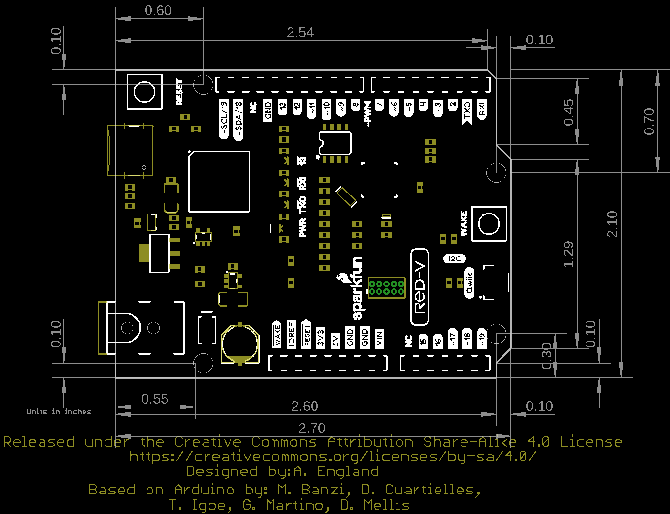
- SparkFun RED-V RedBoard - SiFive RISC-V FE310 SoC

SparkFun RED-V RedBoard - SiFive RISC-V FE310 SoC
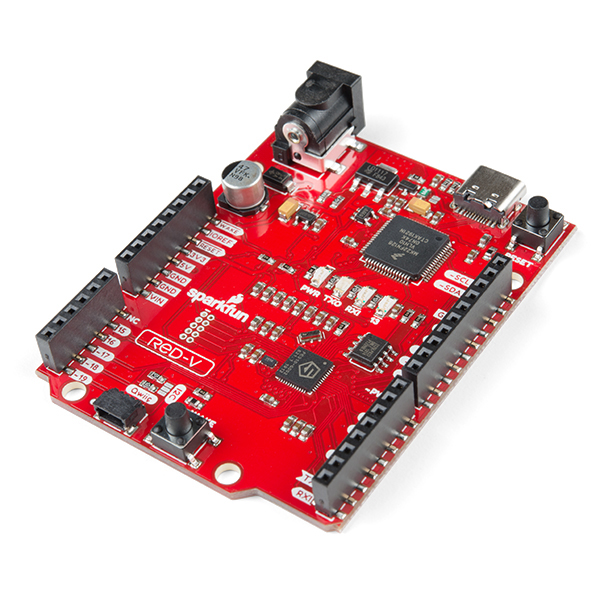
The SparkFun RED-V (pronounced “red-five”) RedBoard is a low-cost, development board featuring the Freedom E310 SoC which brings with it the RISC-V instruction set architecture (ISA). What sets the RED-V RedBoard apart from the rest is the completely open-source approach from hardware to ISA. That means anyone can make full use the microcontroller without requiring royalties, licenses, or non-disclosure agreements.
The RED-V RedBoard comes in the familiar Arduino Uno R3 form factor and includes the SiFive Freedom E310 core, 32MB of QSPI flash, an NXP K22 ARM Cortex-M4 for USB connectivity and operating as a JTAG interface, and a Qwiic connector to make future I2C offerings easy*. The modern USB-C connector makes it easy to program and for more advanced users who prefer to use the power and speed of professional tools, we've also exposed the JTAG connector. Additionally, it comes programmed with a simple bootloader making the RED-V the best way to start prototyping and developing your RISC‑V applications.
The on board Freedom E310 (FE310) is the first member of the Freedom Everywhere family of customizable SoCs from SiFive. Designed for microcontroller, embedded, IoT, and wearable applications, the FE310 features SiFive’s E31 CPU Coreplex, a high-performance, 32-bit RV32IMAC core. Capable of running at 150MHz, the FE310 is among the fastest microcontrollers in the market. Additional features include a 16KB L1 Instruction Cache, a 16KB Data SRAM scratchpad, hardware multiply/divide, a debug module, flexible clock generation with on-chip oscillators and PLLs, and a wide variety of peripherals including UARTs, QSPI, PWMs, and timers. Multiple power domains and a low-power standby mode ensure a wide variety of applications can benefit from the FE310. The RED-V requires Freedom Studio software or a Zephyr RTOS build environment set up to program the board and interface with it.
Note: Please be aware that Qwiic Libraries are not yet available for the Freedom Studio SDK or the Zephyr environment that runs on the FE310. We will update the community when these become available.
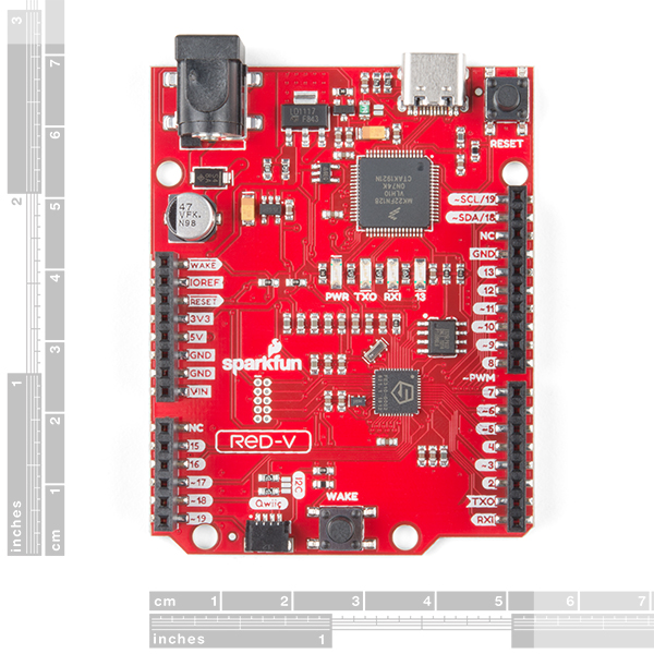
- Arduino R3 Footprint
- Microcontroller: SiFive Freedom E310 (FE310-G002)
- CPU: SiFive E31 CPU
- Architecture: 32-bit RV32IMAC
- Speed: 256 MHz (default), 320MHz (Max)
- Performance: 1.61 DMIPs/MHz
- Memory: 16 KB Instruction Cache, 16 KB Data Scratchpad
- Other Features: Hardware Multiply/Divide, Debug Module, Flexible Clock Generation with on-chip oscillators and PLLs
- Operating Voltage: 3.3 V and 1.8 V
- Input Voltage: 5 V USB or 7-15 VDC Jack
- IO Voltages: Both 3.3 V or 5 V supported
- Digital I/O Pins: 19
- PWM Pins: 9
- SPI Controllers/HW CS Pins: 1/3
- External Interrupt Pins: 19
- External Wakeup Pins: 1 (& button)
- Host Interface (USB-C): Program, Debug, and Serial Communication
- Qwiic Connector
SparkFun RED-V RedBoard - SiFive RISC-V FE310 SoC Product Help and Resources
RED-V Development Guide
November 27, 2019
This guide will help you get the RED-V RedBoard or Thing Plus up and running for the exhaust port. Depending on personal preference, there are a few environments to get started with the boards. All wings report in... we're going in full-throttle.
RED-V RedBoard Hookup Guide
November 22, 2019
This guide will go over the hardware of the RED-V RedBoard.
Core Skill: Programming
If a board needs code or communicates somehow, you're going to need to know how to program or interface with it. The programming skill is all about communication and code.
Skill Level: Expert - You should be extremely comfortable programming on various hardware in several languages.
See all skill levels
Core Skill: Electrical Prototyping
If it requires power, you need to know how much, what all the pins do, and how to hook it up. You may need to reference datasheets, schematics, and know the ins and outs of electronics.
Skill Level: Rookie - You may be required to know a bit more about the component, such as orientation, or how to hook it up, in addition to power requirements. You will need to understand polarized components.
See all skill levels
Comments
Looking for answers to technical questions?
We welcome your comments and suggestions below. However, if you are looking for solutions to technical questions please see our Technical Assistance page.
Customer Reviews
3.5 out of 5
Based on 8 ratings:
3 of 3 found this helpful:
I am very disappointed
I am very disappointed by the lack of Sparkfun response to the USB Drivers for Jlink, and so I have thrown the risc-v board into the junk box.
The ""RED-V Development Guide" page" is out of date. The instructions to install USB drivers for win10/x64 no longer apply because the latest downloaded Freedom Studio no longer provides it. Freedom Studio does supply supply "instDrivers.exe", but that fails to open.
I report my problem to Sparkfun but no response. Later in July, 2 weeks ago, I post a help request in the related Sparkfun forum, but no response yet.
I buy a HiFive1RevB board and try that, and get the same problem. I also try all this again on a different computer, but no success.
I did discover an old 2015 Segger forum comment, that it is not their fault and blames windows. I thought this was going to be a fun project during my vacation time but it turned out to be frustrating misery.
Excellent introduction to RISC-V development
The RED-V features a SiFive FE310 and a Segger JTAG interface. I downloaded the turnkey IDE from SiFive and was running "hello world" in a matter of minutes. If you are an early purchaser, your RED-V may have a wrong R8 value; SparkFun has provided an updated RED-V to correct this, as well as directions on how to re-work R8 on your first RED-V. The impact of incorrect R8 is the PLL clock will not run - but the board defaults to 16MHz crystal oscillator so this may not be a problem.
RED-V includes a 32.768kHz oscillator for the FE310 RTC which just works when enabled.
USB-C might be a little odd for some users but all you need is a cable if you don't already have one.
The FE310 is not a mixed-signal chip - it provides a good amount of I/O but if you need an ADC or DAC, you'll need to connect that via the expansion connectors.
A good RISC-V introduction board.
This board has a SiFive FE310 chip. It's roughly equivalent to a Cortex-M3 chip. ie- 32-bit, no floating point (RV32acimu). I get the impression the FE310 chip is more of a demonstration chip than a serious attempt to take on other ARM microcontrollers. There are not that many peripherals on chip. It only has 16 KiB of on-chip RAM. Still - it's a good RV32 reference design and the onboard J-Link interface makes it easy to use. I bought it as a RISC-V learning platform, so I'm happy with it. If I wanted a RISC-V microcontroller for a product I'd probably be looking at a more featureful GigaDevice chip.
Fantastic board for the FE310-G002
This board is very similar to the SifFive HiFive1 RevB, but with some nice quality of life improvements.
In particular I love the surface mount headers vs through hole. It makes the board much easier to throw around or leave on top of tables or laptops while I'm working with it. The substitution of USB-C for micro is a nice touch. I'll admit I was lacking in USB-C cables, but side-by-side with my other micro-b based boards the connector feels more sturdy and solid. The lack of ESP32 on here I consider a feature as well ;D Not only lowering the price but also decreasing weight and complexity of peripherals to use.
I have a handful of different FE310 based board lying around and I find this is my go to board when I'm just hacking on software or trying to work on the SDK itself.
In general, for the G002 based boards (HiFive1 RevB, and RED-V boards) there is currently as of writing no OpenOCD or Arduino support. Sparkfun does a good job not mentioning this and has a great guide for getting started using this board.
Works good, learning curve isn't that bad...
The RED-V is a semi-clone of the SiFive HiFive1 RevB. The SiFive board has an ESP wifi / bluetooth device on board -- but as far as I can tell it isn't used for anything. It also has an RGB LED. This board has only a single blue LED and no ESP device. Otherwise they appear to be the same.
I was able to download Freedom Studio, install everything and get a demo going within an hour or so. The basic HiFive1 RevB code ran on the RED-V board without issue. Note that the LED count and location must be updated, but otherwise things worked really well. SiFive has done a lot to make Eclipse feel more like a dedicated embedded IDE.
The most difficult thing about the Freedom Studio install was the j-link driver installation. I did it by locating the j-link device in the Win10 device manager and updating the driver with the jlink drivers in the Freedom Studio.
The FE310 has the ability to run code from a QSPI. This is how the RED-V works. However, when it comes to RAM, it's a little limited at 16Kb.
For an intro-board for RISC-V, I'd say this is a great starting point.
Failed on MacOS and ubuntu
Failed for me with:
Mac OS Catalina Ubuntu 20.04.1 LTS
Definitely don't try 32 bit linux (the freedomstudio IDE is not compatible)
Someone else also mentioned this does not work, wish I had read their review before purchasing this. Of the dozens of products I've purchased from sparkfun, this is 1 of 2 I can't get to work (the other is working in diminished capacity). Tried to request help in the forum and it's stuck in review. Things that were massively easier than working with this product.
1) Learning any of the 14 programming languages I've used professionally 2) Hacking my Wii without soldering 3) Founding a 501c(4) and launching a custom LAMP server 4) skyrocketing a friend to #1 singer on myspace with a custom perl script
This thing is configuration awfulness, don't buy, or dear god, please share your secret to unlock!
Or please enjoy chasing your tail with what I think is USB serial interfaces.
Up and running!
Amazing to have ready access to a sifive 32-bit chip. I am just getting started with risc-v, and this is a great learning platform.
This is not a replacement for ARM or AVR micros... library support is still very limited. But it supports the tool chain and thus provides access to the ISA.
Go for it. At this price it’s a no brainer. I recommend Anthony J Dos Reis’s book on risc-v assembly as a companion to the board.
Toolset has a couple of rough edges
I have a fair amount of experience with earlier incarnations of this artchitecture -- MIPS, Microblaze and Mico2 -- and their associated development environments. RISC-V promises to unify and rationalize these architectures by adding better thought out interrupt handling, startup and power control. In recent years I've used this processor type to implement industrial protocols (Ethercat, Powerlink, Modbus) because you get good performance with a modest clock speed and device, if a 'soft' processor, only has a small footprint.
This board works flawlessly but there are some glitches with Freedom Studio, the Eclipse based IDE that SIFive provide for the processor. There needs to be more attention paid to documentation detail and in particular the JTAG debugger. These USB hosted debuggers either work first time or they refuse to work, period. For this Segger one the Windows drivers won't install (and the installer won't tell you why) and Linux ones may have installed but the debug server can't find them. I've had 40-50 years experience with bare metal programming so I think of a debugger as a 'nice to have' feature but for most programmers this is a showstopper. This isn't a problem specifically with Segger but its a generic issue that needs to be addressed if the product is to be viable, its no use claiming that "It works on my Golden Computer". It is possible to make these units trouble free so why not deal with it?
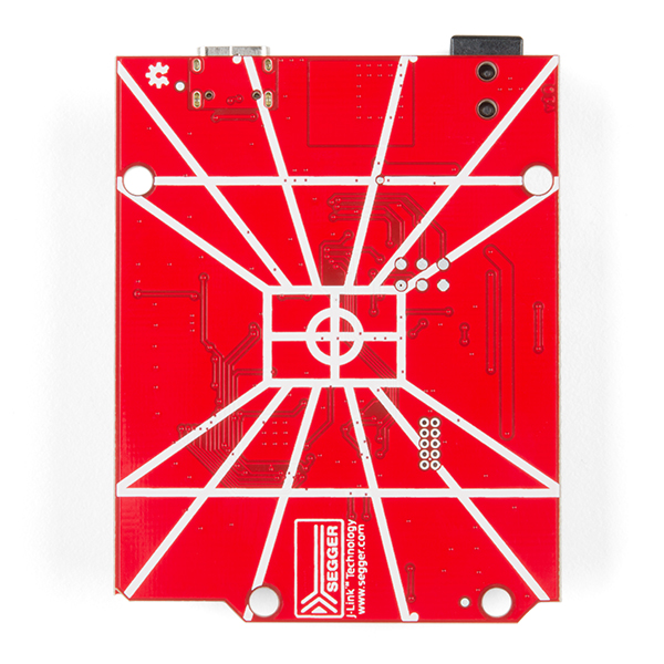
kudos on the targeting computer silk screen
I'd have rather seen more time spend on adding useful information to the silk screen, such as indicating which connectors are JP2, JP10, JP11, and JP13, than some silly Star Wars reference.
Hi there, it sounds like you are looking for technical assistance. Based on your comments below, it sounds like you might be unfamiliar with reading the electronic schematics. Unfortunately, the comments section isn't the appropriate channel for technical assistance; please use the link in the banner above, to get started with posting a topic in our forums. Our technical support team will do their best to assist you.
That being said, those parts are listed under the Headers section of the schematic; therefore, they refer to the vertical headers on the board (the black pieces that you can stick jumper wires into). The silk on the board is based on the standard Arduino board silk, since this board uses the Arduino Uno form factor. Additionally, most manufacturers also don't include part designators (i.e. "JP2") on their PCBs due to the limited board space and clutter with that labeling.
As a tip, if you open the Eagle files using Eagle (the software is free for hobbyists), you can highlight the connections; this should makes things easier for you to follow. (Use the "eyeball" looking icon and then click on the nest ("connection") or part ("component") of interest, this will highlight the connection on both the schematic and board file.) For more details on using the Eagle software, there is an abundance of resources available online including basic tutorials from Autodesk, the software provider.
I'm very familiar with reading schematics, but not familiar with the Eagle convention for naming signals. I'll take any future support questions to the forums as you suggest.
I have quite a few development boards within arm's reach on my bench, and grabbing a dozen or so from various manufacturers, I see that every one of them label (i.e. "JP2") the headers on the silk screen.
You said: "What sets the RED-V RedBoard apart from the rest is the completely open-source approach from hardware to ISA. That means anyone can make full use the microcontroller without requiring royalties, licenses, or non-disclosure agreements."
Apparently not true?
On your page located at: https://learn.sparkfun.com/tutorials/red-v-development-guide, there is the warning:
" Warning: Do NOT attempt to reprogram the NXP K22 ARM Cortex-M4. It has proprietary Segger firmware flashed onto the chip, which allows it to upload programs the SiFive Freedom E310 core. Reprogramming the NXP K22 ARM Cortex-M4 will overwrite the firmware and you will no longer be able to reprogram the board. To replace the firmware, you will need to purchase a license from Segger along with one of their programmers."
So, it appears to me that this may not be "completely open" as the boot loader is proprietary. Or am I missing something here?
Thanks!
The Firmware for the USB to JTAG debugger is proprietary, just like firmware for many ARM based USB to Serial converters. Any code written utilizing the RISC-V ISA however, will be completely open and frozen to be forever compatible with the ISA. We've also broken out the JTAG connections if you'd like to program the board over JTAG using your own debugger. Anybody can make full use of the microcontroller however without requiring licenses or NDAs. The bootloader itself is contained within the FE310 and basically says "Jump to user code @0x20001000"
Since we had to program the USB-to-JTAG in house, we don't want anybody accidentally bricking an important comms IC, as usually this (firmware running on conversion IC's) is not something that is accessible to the customer or even us at SparkFun. So I guess everything isn't completely open :/
With that name of course it has a standby mode.
Well done.
The Always-On (AON) block of the FE310 can be programmed to do all sorts of neat power management stuff, including shutting down the voltage regulator for the main core's power. You can then program it to wake back up via the WAKE button, or a time-based interrupt, as the AON block has it's own external oscillator.
But can it bullseye a womp rat?
Anyone buying this be aware - the instructions are out of date for windows 10. There is no executable you can run to update the drivers for the JLink. You need to download and install Seggers Risc IDE, run it up with a simple demo example - use the HiFive1_RevB samples. Seggers will update the drivers for you. Then once you get it working in there - very easy. You can go back and use the Freedom IDE if you want.
The schematic for this board is a mess!
For example, what is the blue LED connected to? On the schematic, it's shown as connected to "SPI_SCK/1". What is that? There's no other reference to SPI_SCK/1 on the schematic. On the first page, there's a "SPI_SCK/2", which is connected to pin 31 on the RISC-V, where it's labeled "IO5 SPI1_SCK" -- is this the same as "SPI_SCK/1"?? This is clear as mud... Grrrrr. Help!
Hi, this is how Eagle denotes when signals are connected to different sheets. The reference on the first page is simply saying "I am connected to SPI_SCK on sheet two". Going to sheet two will then show you that the SPI_SCK there is connected to sheet 1. Again this is how Eagle keeps track of schematics between multiple sheets, otherwise it would be quite difficult to look at more complex designs. Hope this helps.
Yes, that helps. Thanks. I don't use Eagle, so I'm not familiar with its conventions.
Given that the FE310-G002 datasheet specifies FMAX of 320MHz and my Red-V (R8 100ohms) appears to be stable at 320MHz, perhaps the product page could replace "150MHz" with "320MHz"?
Thanks again Dana, updated.
Has anyone tried this board with Segger Embedded Studio for RISC-V?
https://www.segger.com/downloads/embedded-studio
Based, upon the information on their website, it looks like it is compatible. I hopped on the Google machine and there seems to be a few examples out there too.
nice
It looks like this board is using the E310-G000 chip. Some browsing on the wifi was site indicates the G002 version has hardware I2c support, which seems like a Good Thing. Will SparkFun be making a version of Red-v with the G002 chip?
Thanks! Really looking forward to getting in to risc-v. <insert obligatory reference to Hackers film here>
https://getyarn.io/yarn-clip/628bad89-267a-431c-88ce-cbd7f9e9f0e7
This version is actually made with the G002 chip. Where did you see that we had the G000 as I'd like to update that language. Thanks!
The SparkFun 'Features' for this board list clock rate of 150MHz but the -G002 datasheet lists FMAX of 320MHz - I don't see anything to indicate these chips are binned into speed grades. Is the FE320-G002 on the RedBoard capable of operating at 320MHz?
Should be, you'll inevitably have to do some fiddling with your PLL and possibly the external oscillators but it is hypothetically possible.
With R8 changed to 100 ohms, it's easy to change the clock rate from the HFXOSC value of 16MHz.
Though this function appears to hang every now and again - I believe it's possibly because the metal code is not observing the required 100uS delay before checking PLL lock in the Freedom Metal code.
The chip warms up quite a bit when running at 320MHz :-)
Awesome! I never had time during development to fiddle around with overclocking, I'll get this added to the product description. Thanks Dana
Technically, this isn't over-clocking, since the chip datasheet has an FMAX of 320MHz. The PLL can produce up to 384MHz, but I don't have high hopes that'll be stable. It's also possible to run the part at a very low clock rate, with proportionately less power consumption. I've tested it at 2MHz.
I'll give it a try as soon as I have the 'fixed' Red-V (and also re-work the 'first run' one). Fortunately I've figured-out how to get Freedom Metal to program the PLL (it bricks the 'first run' one until I jumper across R8 temporarily to program it :-))
Aaaaaand I have updated the links on the respective product pages and tutorials for FE310-G002. ^_^
Hmm, looks like the manual in the Documents tab was linked to the G000 version. I'll look into it to update the respective links as well.