- Home
- Product Categories
- RISC-V
- SparkFun RED-V Thing Plus - SiFive RISC-V FE310 SoC

SparkFun RED-V Thing Plus - SiFive RISC-V FE310 SoC
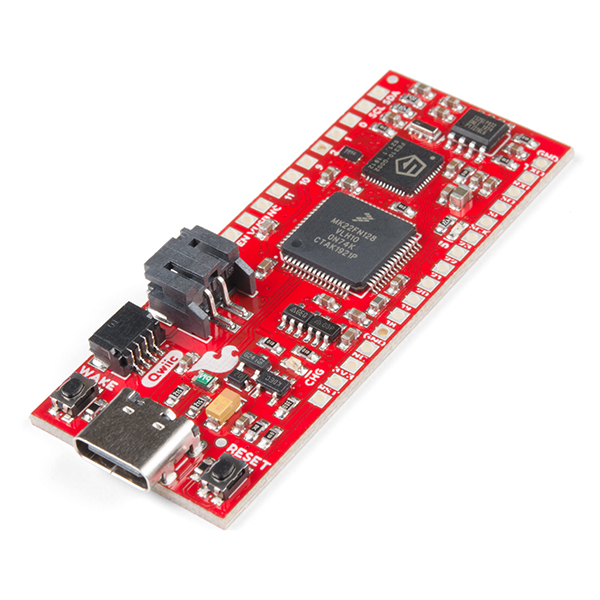
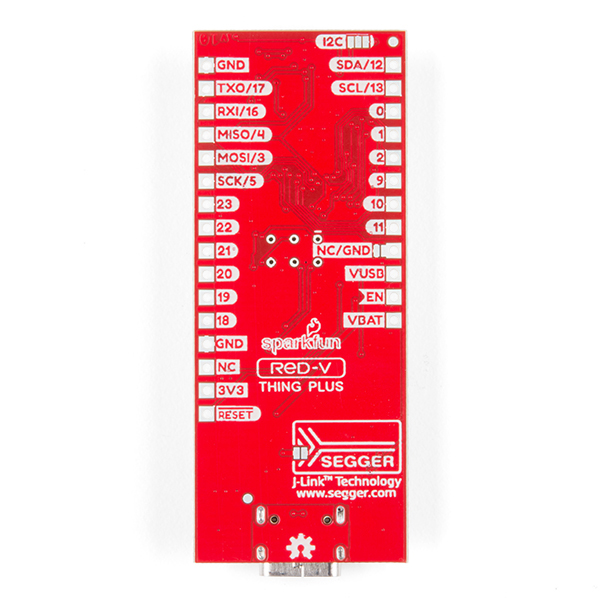
The SparkFun RED-V (pronounced “red-five”) Thing Plus is a low-cost, development board in our popular Thing Plus footprint and adds in the Freedom E310 core and RISC-V instruction set architecture (ISA). What sets the RED-V Thing Plus apart is the completely open-source approach from hardware to ISA. That means anyone can make full use the microcontroller without requiring royalties, licenses, or non-disclosure agreements.
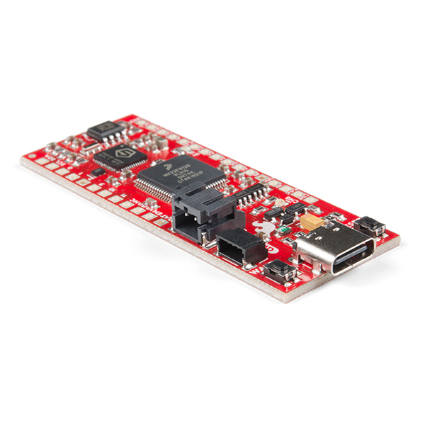
The RED-V Thing Plus comes programmed with a simple bootloader The modern USB-C connector makes it easy to program over USB connectivity or use as a JTAG interface via the FE310's NXP K22 ARM Cortex-M4. Since the Thing Plus footprint is also Feather-compatible, you can take advantage of existing shield options. We have included a Qwiic connector to enable future use of our handy plug-and-play I2C Qwiic Connect System which means no soldering or shields are required*. With so much freedom & growing industry functionality, the SparkFun RED-V Thing Plus is an ideal choice for your RISC-V project.
The on board Freedom E310 (FE310) is the first member of the Freedom Everywhere family of customizable SoCs from SiFive. Designed for microcontroller, embedded, IoT, and wearable applications, the FE310 features SiFive’s E31 CPU Coreplex, a high-performance, 32-bit RV32IMAC core. Running at 150MHz, the FE310 is among the fastest microcontrollers in the market. Additional features include a 16KB L1 Instruction Cache, a 16KB Data SRAM scratchpad, hardware multiply/divide, a debug module, flexible clock generation with on-chip oscillators and PLLs, and a wide variety of peripherals including UARTs, QSPI, PWMs, and timers. Multiple power domains and a low-power standby mode ensure a wide variety of applications can benefit from the FE310. The RED-V Thing Plus requires Freedom Studio software or a Zephyr RTOS build environment set up to program the board and interface with it.
Note: Please be aware that Qwiic Libraries are not yet available for the Freedom Studio SDK or the Zephyr environment that runs on the FE310. We will update the community when these become available.
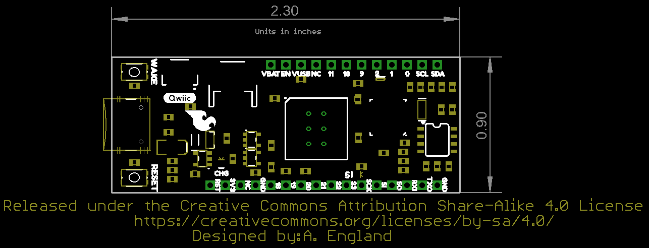
- Feather Compatible Footprint
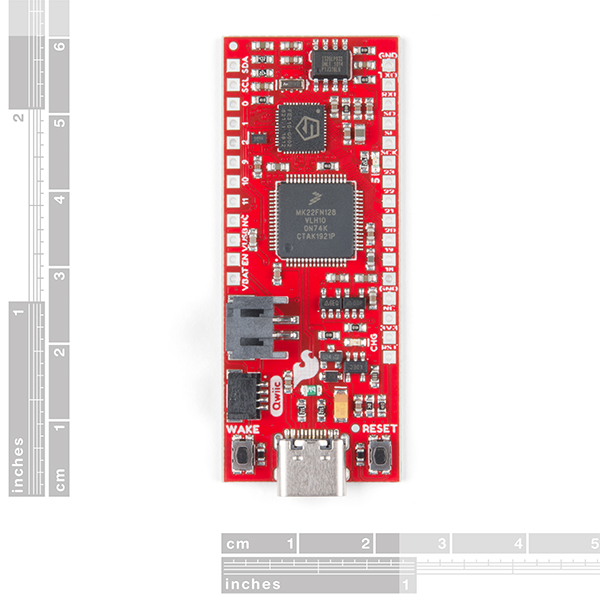
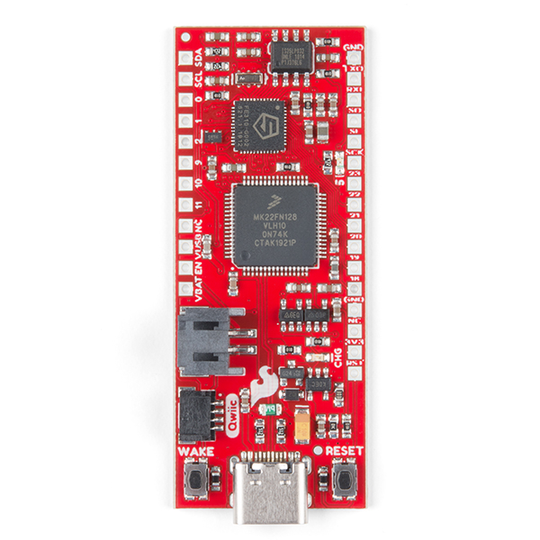
- Microcontroller: SiFive Freedom E310 (FE310-G002)
- CPU: SiFive E31 CPU
- Architecture: 32-bit RV32IMAC
- Speed: 150MHz
- Performance: 1.61 DMIPs/MHz
- Memory: 16 KB Instruction Cache, 16 KB Data Scratchpad
- Other Features: Hardware Multiply/Divide, Debug Module, Flexible Clock Generation with on-chip oscillators and PLLs
- Operating Voltage: 3.3 V and 1.8 V
- External Wakeup Pins: 1 (& button)
- Host Interface (USB-C): Program, Debug, and Serial Communication
- Qwiic Connector
SparkFun RED-V Thing Plus - SiFive RISC-V FE310 SoC Product Help and Resources
RED-V Development Guide
November 27, 2019
This guide will help you get the RED-V RedBoard or Thing Plus up and running for the exhaust port. Depending on personal preference, there are a few environments to get started with the boards. All wings report in... we're going in full-throttle.
RED-V Thing Plus Hookup Guide
November 22, 2019
This guide will go over the hardware of the RED-V Thing Plus.
Core Skill: Programming
If a board needs code or communicates somehow, you're going to need to know how to program or interface with it. The programming skill is all about communication and code.
Skill Level: Expert - You should be extremely comfortable programming on various hardware in several languages.
See all skill levels
Core Skill: Electrical Prototyping
If it requires power, you need to know how much, what all the pins do, and how to hook it up. You may need to reference datasheets, schematics, and know the ins and outs of electronics.
Skill Level: Rookie - You may be required to know a bit more about the component, such as orientation, or how to hook it up, in addition to power requirements. You will need to understand polarized components.
See all skill levels
Comments
Looking for answers to technical questions?
We welcome your comments and suggestions below. However, if you are looking for solutions to technical questions please see our Technical Assistance page.
Customer Reviews
No reviews yet.
Assuming Q1 in the schematic is a p-FET to cut power from battery when USB is applied, it is placed incorrectly in the schematic: the source should be on the high side and the drain should be on the low side. As it is now, the source/drain protection diode in most discrete FETs will pass current in that polarity regardless of what is going on at the gate voltage.
I think the point of Q1 is not to cut the power from the battery but to isolate the battery from the USB's higher voltage. The point of using a transistor is to minimize voltage drop when no USB power is present.
I checked in with one of our engineers and he understands your concern, but the circuit has been tested and we have been using this design pretty heavily, on a lot of other boards, for several years. However, if you feel that we are grossly mistaken, please feel free to test the circuit and post your findings on the issue in our forum. I would be happy to pass the information on to the engineering team for them to investigate further at that point.
Platform IO lists the SparkFun RED-V Thing Plus hardware as FE310 320MHz, 16KB RAM, 16MB Flash. This page says 150 MHz and 4 MB Flash. Which is accurate?
The RedVThingPlus schematic Power Supply section states VIN: 2.5-6.0V. However, the supply drives a 3.3V low dropout regulator with a typical dropout voltage of 0.25V. Hence, it would seem this is a typo and should read VIN: 3.55 - 6.0V.
Is there a recommended interface cable or header for the JTAG connector on the back of the board? I would have thought the SEGGER 6-Pin Needle Adapter would work, but it seems to be lacking board features for this.
I'd use this guy to tap into that 2x3 on the back, however please note that this isn't a JTAG connector, but the connector to program for the USB->JTAG interface IC. JTAG is only accessible over USB on this product. If you want to access JTAG lines on the FE310, you'll have to snag a Regular old RED-V
So is this statement not true?
"The RED-V Thing Plus comes programmed with a simple bootloader The modern USB-C connector makes it easy to program over USB connectivity or use as a JTAG interface via the FE310's NXP K22 ARM Cortex-M4. For more advanced users who prefer to use the power and speed of professional tools, we've also exposed the JTAG connector."
Looks like a copy/paste error. I'll get that last sentence removed.
first question: is this board arduino compatible? second; Why is there a MK22FN128 processor with very little breakout(analysing the schematic) while the SiFive E31 CPU (being main processor ) has lots of breakouts. Isn't it a bit of a waste to just connect a few wires to the MK22FN128. Why dont you use a smaller version to perhaps save cost or create dual processors
In it's current state, this board is not Arduino IDE compatible. The MK22FN128 Processor serves as a USB->JTAG interface (Pretty neat) to the FE310. Although it has a ridiculous amount of unused pins (It's an MCU doing a job well below it's pay-grade), this module is necessary as a USB->JTAG device to program the FE310.
How much flash?
4 megabyte! All the flash space starts at 0x20000000 and is actually located on an external, QSPI accessible flash chip
The flash size should listed on the description and features.
Also, does it support DFU standard? What about WebUSB?