- Home
- Product Categories
- Distance
- SparkFun Qwiic dToF Imager - TMF8821

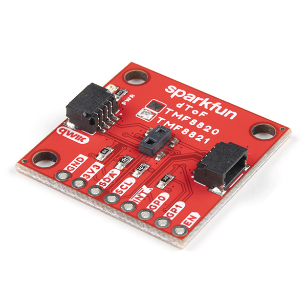
SparkFun Qwiic dToF Imager - TMF8821
The SparkFun Qwiic dToF TMF8821 Imager is a direct time-of-flight (dToF) sensor that includes a single modular package with an associated Vertical Cavity Surface Emitting Laser (VCSEL) from AMS. The dToF device is based on Single Photon Avalanche Photodiode (SPAD), time-to-digital converter (TDC) and histogram technology to achieve a 5000mm detection range. Due to its lens on the SPAD, it supports 3x3, 4x4, and 3x6 multizone output data and a very wide, dynamically adjustable field of view. A multi-lens-array (MLA) inside the package above the VCSEL widens up the FoI (field of illumination). All processing of the raw data is performed on-chip and the TMF8821 provides distance information together with confidence values on its I2C interface. The high performance on-chip optical filter blocks most of the ambient light, and enables distance measurements in dark and sunlight environments.
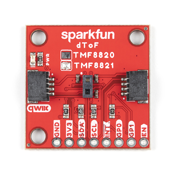
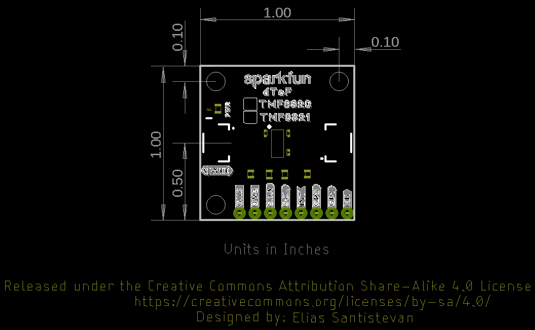
To make it even easier to get your readings, all communication is enacted exclusively via I2C, utilizing our handy Qwiic system so no soldering is required to connect it to the rest of your system. However, we still have broken out 0.1”-spaced pins in case you prefer to use a breadboard. The TMF8821 offers two configurable GPIO pins and one enable (EN) pin, which are broken out as PTH pads. The board also includes a power LED and I2C pull-up resistors, each configurable via jumpers. This version has a footprint that uses the Qwiic Standard size (1.0in. x 1.0in.). For a smaller footprint, check out our Qwiic Mini dToF TMF8821 Imager board!
This sensor is great for projects such as distance measurement for camera autofocus - Laser Detect Autofocus - LDAF (mobile phone), presence detection (computing and communication), object detection and collision avoidance (robotics), and light curtain (industrial).
Note: CLASS 1 LASER PRODUCT CLASSIFIED IEC 60825-1 2014.
Important: We recommend a microcontroller with enough flash to run your program code. Sorry, Uno's (or any development board using the ATmega328P) are out. We recommend choosing either an Artemis Thing Plus, ESP32 Thing Plus, or comparable device as your development board.
The SparkFun Qwiic Connect System is an ecosystem of I2C sensors, actuators, shields and cables that make prototyping faster and less prone to error. All Qwiic-enabled boards use a common 1mm pitch, 4-pin JST connector. This reduces the amount of required PCB space, and polarized connections mean you can’t hook it up wrong.
- Operating Voltage
- 2.7V to 3.6V
- (typically 3.3V via Qwiic cable)
- Current Consumption
- 8µA (standby)
- 57mA (active)
- AMS TMF8821 Multi-zone Time-of-Flight Sensor
- Direct ToF technology with high sensitivity SPAD detection
- 4x4 configurable multi-zone configuration with multi-object detection
- Fast Time-to-Digital Converter (TDC) architecture
- Sub-nanosecond light pulse
- On-chip histogram processing
- High performance on-chip sunlight rejection filter and algorithm
- Measurement Range: 10mm to 5000mm @ 30Hz
- Light Source: Class 1 940nm VCSEL
- Field of View: adjustable up to 63° diagonally
- Max Read Rate: up to 30Hz
- 2x Qwiic Connectors
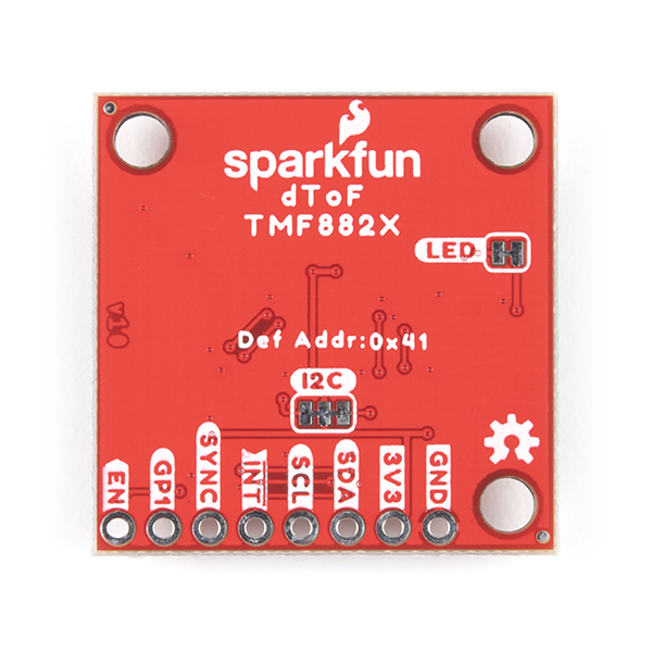
- I2C Address: 0x41
- Operating Temperature Range
- -30°C to +70°C
- Breakout Pads
- 1x Ground
- 1x Power
- 1x I2C Port
- 1x Interrupt
- 2x GPIO
- 1x Enable
- Power LED (configurable via jumper)
- I2C pull-ups (configurable via jumper)
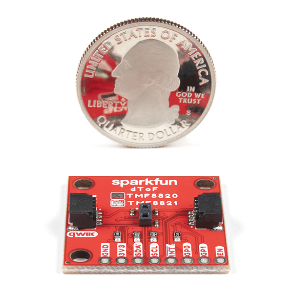
- Board Dimensions: 1.0" x 1.0" (2.54cm x 2.54cm)
SparkFun Qwiic dToF Imager - TMF8821 Product Help and Resources
Qwiic dToF Imager (TMF882X) Hookup Guide
April 14, 2022
Getting started with the AMS dToF imagers (TMF8820 and TMF8820).
Core Skill: Programming
If a board needs code or communicates somehow, you're going to need to know how to program or interface with it. The programming skill is all about communication and code.
Skill Level: Competent - The toolchain for programming is a bit more complex and will examples may not be explicitly provided for you. You will be required to have a fundamental knowledge of programming and be required to provide your own code. You may need to modify existing libraries or code to work with your specific hardware. Sensor and hardware interfaces will be SPI or I2C.
See all skill levels
Core Skill: Electrical Prototyping
If it requires power, you need to know how much, what all the pins do, and how to hook it up. You may need to reference datasheets, schematics, and know the ins and outs of electronics.
Skill Level: Rookie - You may be required to know a bit more about the component, such as orientation, or how to hook it up, in addition to power requirements. You will need to understand polarized components.
See all skill levels
Comments
Looking for answers to technical questions?
We welcome your comments and suggestions below. However, if you are looking for solutions to technical questions please see our Technical Assistance page.
Customer Reviews
1 out of 5
Based on 1 ratings:
1 of 1 found this helpful:
Very difficult to use.
This has been a real disappointment. It is a great concept, but I found it very difficult to use in a real application. The documentation is very poorly organized and written. It has lots of detail but little overview or “how to” application guidance. Terms are not well defined and difficult to understand without getting down into the detailed spec sheet, and sometimes not even then. The libraries and examples help with basic connectivity but do little to clarify how to do anything useful. Some specific examples: the relationships between the various timing parameters are almost impossible to figure out, and the mapping between zones, channels, and subchannels is not easy to determine especially since they change from mode to mode.
This device really needs to use interrupts. The examples use a polling scheme which occupy the host from tens to many hundreds of milliseconds for each reading – a huge waste of the resources of a high performance processor especially at high sample rates. One of the weaknesses of the Qwiic system is that it does not provide a way to use interrupts without soldering a separate wire – which defeats the purpose of Qwiic.
As an “imager” I would think that the most fundamental thing would be to be able to create a simple X-Y matrix of distance measurements. Yet after many hours of wandering through the details of the spec sheets and experimentation, I have been unable to do this simple thing in the 3x6 mode. It seems that the information is coming out in a different pixel location than I would expect from the zone maps. The field of view seems to be very different than what I would expect from the spec sheets (note that not all the pixels seem to be the same size). Part of the problem is that there seems to be about a 10 or 20 mm offset in the distance values so I am not sure where the reference plane is. This may be a defective device, but due to my difficulty in getting things to work properly, I cannot rule out the possibility that I am doing something wrong. But the bottom line is that this should not be so hard.
In an effort to simplify a bit, I went back to the 3x3 mode. This seems to work better. A 100 mm reported range is actually at 125 mm. But the results seem to come out on the right channels.
Based on my experience, this is not a device for the casual hobbyist, and I would not recommend it for even more advanced users unless you are willing to spend hours reading spec sheets and code. I am interested to see what others have experienced trying to use this device.
There is a much simpler Arduino driver available on the ams.com website https://ams.com/tmf8821. It was written to fit within the memory footprint of the Arduino Uno R3, also tested on SAMD21 RedBoard Turbo and SAM D21 Mini breakout boards with the appropriate USB serial modifications.