- Home
- Product Categories
- Audio Boards
- MIKROE BUZZ 3 Click

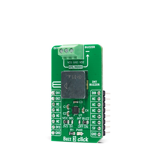
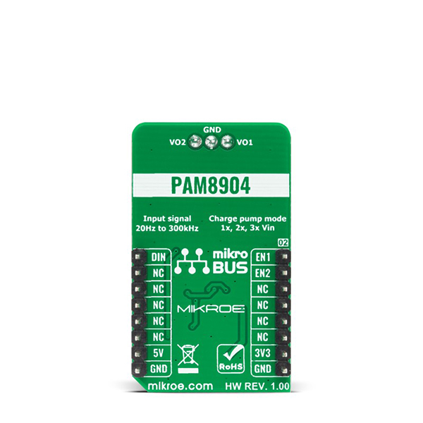
Buzz 3 Click is a compact add-on board that contains a sounder driver that produces higher volume with a lower current. This board features the PAM8904, a piezo-sounder driver with an integrated Multi-Mode charge pump boost converter from Diodes Incorporated. With its wide input signal range of 20Hz to 300kHz, the PAM8904 can drive a sounder load of up to 15nF, providing a 9V output. It enables the selection of three different piezo sound pressure levels, keeps current consumption low, and extends battery life by employing built-in automatic shutdown and wake-up functions. This Click board™ is suitable for a variety of battery-powered applications, including medical systems, alarm clocks, home appliances, and security devices.
Buzz 3 Click is supported by a mikroSDK compliant library, which includes functions that simplify software development.
Buzz 3 Click is based on the PAM8904, a piezo-sounder driver with an integrated Multi-Mode charge pump boost converter from Diodes Incorporated. The PAM8904 is a switching driver with a multi-mode charge pump for piezo-sounder. Operating at a fixed frequency of 1MHz, the PAM8904 can drive a sounder load of up to 15nF, providing a 9V output with a minimal component footprint. For adjusting the piezoelectric sounder sound volume, the charge pump can operate in either of a 1x, 2x, or 3x mode. It features thermal shutdown, over-current, and voltage protection, under-voltage lock-out, and provides a small inrush current, low EMI, and high efficiency.
The sounder driver helps to keep current consumption low and battery life long by employing built-in automatic shutdown and wake-up functions. For example, active current consumption is just 300µA in 1x mode, with an input voltage of 3V, input frequency of 4kHz, and driving a 15nF piezo. In shutdown mode, the quiescent current is less than 1µA.
The Charge Pump Mode pins, EN1 and EN2, are used to set the charge pump into mode 1xVDD, 2xVDD, 3xVDD, or they can be used to put the PAM8904 into a forced low-current Shutdown Mode. When one or both of the EN pins are pulled high, the device enters the Normal Operation Mode. Once the PAM8904 senses a valid signal on the DIN pin, the charge pump will start and provide the desired voltage on the VOUT pin, and the output drive lines labeled as VO1 and VO2 will become active after a period of between 270μs and 350μs depending on the selected Mode. If a valid signal on the DIN line disappears, the PAM8904 will detect that disappearance and then wait 42ms to ensure its disappearance. If even after this period there is no valid signal on the DIN line, the PAM8904 switches to low-current Standby Mode.
Buzz 3 Click establishes communication with MCU using several GPIO pins routed on the RST, AN, and PWM pins of the mikroBUS™ socket labeled as EN1, EN2, and DIN. There is also a jumper setting available labeled as INT BUZZ used to choose between single-ended and differential load configurations as well as between driving either the onboard piezo-sounder or an externally connected piezo-sounder.
This Click board™ is designed to operate with both 3.3V and 5V logic voltage levels selected via the VCC SEL jumper. It allows for both 3.3V and 5V capable MCUs to use the GPIO communication lines properly. However, the Click board™ comes equipped with a library that contains easy to use functions and an example code which can be used, as a reference, for further development.
- Interface: GPIO, PWM
- Compatibility: mikroBUS™
- Dimensions: 42.9 x 25.4mm
- Input Voltage: 3.3V or 5V
- Supply Voltage: Min. -0.3V, Max. 3.6V
- Maximum Output Voltage: 15V
- Input Signal Frequency Range: Min. 0.02kHz, Typ. 4kHz, Max. 300kHz
- Operating Temperature Range: Min. -40°C, Max. +85°C
MIKROE BUZZ 3 Click Product Help and Resources
Comments
Looking for answers to technical questions?
We welcome your comments and suggestions below. However, if you are looking for solutions to technical questions please see our Technical Assistance page.
Customer Reviews
No reviews yet.