- Home
- Product Categories
- Capacitive
- MIKROE TouchKey 3 Click

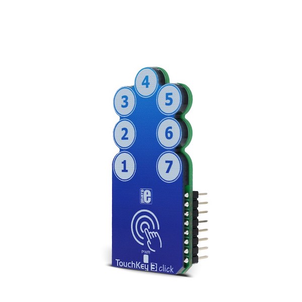
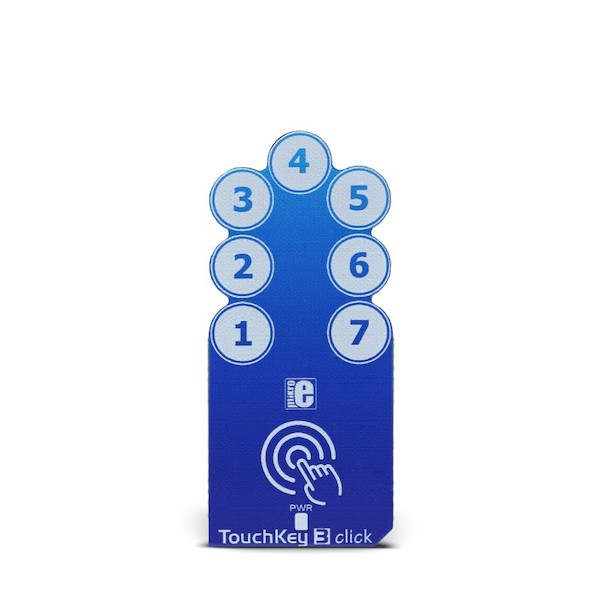
There are many kinds of touch sensors on the market, but every one of them has some unique features that make it stand out from the crowd. TouchKey 3 Click is equipped with seven advanced capacitive sensors, based on the proprietary QTouch® technology. Besides quite a large number of QTouch® capacitive sensor channels, TouchKey 3 Click also offers some additional features, such as the Adjacent Key Suppression (AKS®), a technology that ensures correct button press, even when the touch sensing pads are placed close to each other.
With its many sensing channels and their advanced sensing technologies, TouchKey 3 really stands out from the crowd. It can be used as a multi-button control pad for various embedded applications, replacing mechanical buttons, which are typically prone to malfunctions, with elegant and durable touch sensing pads. Since it can detect touch through 5mm thick layer of plastic, TouchKey 3 is covered with a protective plastic coating, which makes the Click board™ even more robust and wear-proof.
TouchKey 3 Click uses the AT42QT1110, an 11-key QTouch® Touch Sensor IC from Microchip. It can be configured in several different ways, depending on the application: it can be used to support more or less sensor channels, to support direct outputs for an interrupt triggering on a specific channel, to have its #CHANGE output pin used for triggering one global interrupt whenever one of the sensors detects a touch event, or to improve the power consumption by employing the SYNC input signal for triggering sensing bursts in specific time intervals.
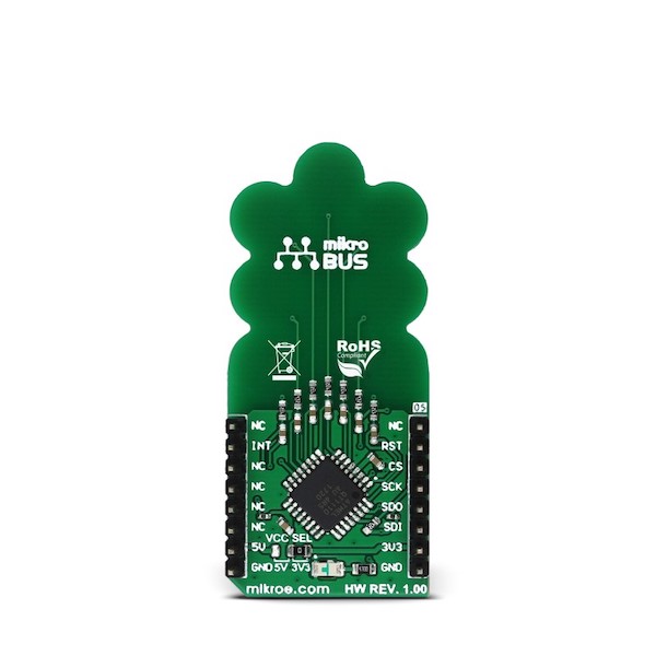
TouchKey 3 Click uses 7 capacitive sensing channels, with the #CHANGE pin routed to the INT pin of the mikroBUS™, so that an interrupt can be triggered if any of the sensors detect a touch event, for example. This can be used to trigger an SPI read cycle only when the key is actually pressed, avoiding the need for constant polling of the AT42QT1110’s registers. However, the behavior of the #CHANGE pin is programmable and more information about its functionality can be found in the AT42QT1110 datasheet. The SYNC pin is pulled high and it is not used, allowing the Click board™ to run in the Free Run mode, which enables the fastest key press detection times.
#RESET pin of the AT42QT1110 is routed to the RST pin of the mikroBUS™ and it is used to reset the device and reinitialize its working parameters - either with values stored in the EEPROM or the default values that are loaded into the RAM, in case the EEPROM does not contain any saved values. SPI will not be available for 160ms after the RESET event has occurred. To reset the device, this pin should be pulled to a HIGH logic level.
The AT42QT1110 sensor has internal registers that are used for configuring the working parameters of the device. Device Mode register is one of the important config registers and it is used to control the overall operation of the Click board™. Bit KEY_AC of the Device Mode register is used to set the detection triggering mode: 0 by SYNC pin or 1 by internal timer (should be set to 1, since the SYNC pin is pulled to a HIGH logic level); MODE bit: 0 for 7, or 1 for 11 channels configuration (should be set to 0 for 7 channels operation); SIGNAL bit: 0 for serial, or 1 for parallel; SYNC bit: 0 for rising edge, or 1 for zero level detect (disregarded, since the KEY_AC is set to 1); REPEAT TIME bit field: these four bits set the repeat time between the scanning intervals. If the REPEAT TIME is set to 0, the new scanning cycle will be performed immediately after the previous cycle, allowing for the fastest touch detection. The value of this bitfield is multiplied by 16ms to get the final repeat time.
TouchKey 3 Click also features signal processing in order to provide better button detection. Adjacent Key Suppression (AKS®) technology can be configured on each channel. A group of channels that has the AKS® enabled will be processed, so that only the detected key will remain active, while other sensors will be disregarded. The other sensors with the AKS® enabled will be activated only when the currently active key is released. The sensor channels for which AKS® is not selected will retain the ability to sense touch simultaneously. This technology allows better key accuracy and less false detections in applications where key press detection precision is required.
The Detection Integration (DI) is another technology that is used to better sense the key press. When the button is first press, a counter is started. If the counter expires and the sensor channel still detects a key press, that keypress will be declared as true. Else it will be disregarded as false. This serves as a kind of debouncing and prevents false detections. DI technology is implemented per sensor.
The AT42QT1110 IC has EEPROM memory, which can be used to store current RAM settings. All the registers are kept in RAM and after the power-on reset event (POR), the values stored in the EEPROM memory will be automatically copied to the registers. Else, the registers will be loaded with the default values.
All these functions can be accessed and configured via the SPI bus. The SPI communication can be either in Quick SPI mode or full SPI mode. While working in the Quick SPI mode, the device will send a sequence of 7 bytes which contain the essential data such as detection status and error status of the channels. In this mode, no host MCU commands are required and this sequence will be clocked out continuously from the AT42QT1110 IC. Quick SPI mode is enabled by setting the SPI_EN bit in the Comms Options setup register. All the SPI pins, along with the chip select pin, are routed to the appropriate pins on the mikroBUS™.
Onboard SMD jumper labeled as VCC SEL is used to select the power supply and logic voltage level. This Click board™ can work with both 3.3V and 5V MCUs.
The provided TouchKey 3 Click library contains functions that are used to configure the device and read touch events in a comprehensive and intuitive manner. The included example application demonstrates usage of these functions and it can be used as a reference for a custom design.
- Interface: GPIO, SPI
- Compatibility: mikroBUS™
- Dimensions: 57.15 x 25.4mm
- Input Voltage: 3.3V or 5V
Comments
Looking for answers to technical questions?
We welcome your comments and suggestions below. However, if you are looking for solutions to technical questions please see our Technical Assistance page.
Customer Reviews
No reviews yet.