- Home
- Product Categories
- Audio Connectors
- Audio Jack 3.5mm

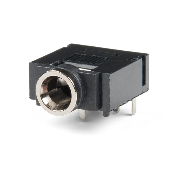
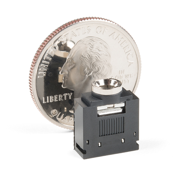
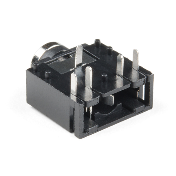
Low profile 3.5mm stereo audio jack.
Audio Jack 3.5mm Product Help and Resources
TeensyView Hookup Guide
March 16, 2017
A guide to using the TeensyView OLED board to display text and graphics.
Analog MEMS Microphone (VM2020) Hookup Guide
February 9, 2023
Get started with the SparkFun analog MEMS microphone breakout board! In this tutorial, we will be connecting the differential MEMS microphone to an Arduino using the WM8960 audio codec.
Audio Codec Breakout - WM8960 Hookup Guide
January 26, 2023
The SparkFun Audio Codec Breakout - WM8960 is a low power, high quality stereo codec chock full of features. In this tutorial, some of these features by using an Arduino microcontroller to configure the audio codec and pass audio to the headphone or speaker channels.
Connector Basics
January 18, 2013
Connectors are a major source of confusion for people just beginning electronics. The number of different options, terms, and names of connectors can make selecting one, or finding the one you need, daunting. This article will help you get a jump on the world of connectors.
Core Skill: Soldering
This skill defines how difficult the soldering is on a particular product. It might be a couple simple solder joints, or require special reflow tools.
Skill Level: Noob - Some basic soldering is required, but it is limited to a just a few pins, basic through-hole soldering, and couple (if any) polarized components. A basic soldering iron is all you should need.
See all skill levels
Comments
Looking for answers to technical questions?
We welcome your comments and suggestions below. However, if you are looking for solutions to technical questions please see our Technical Assistance page.
Customer Reviews
5 out of 5
Based on 4 ratings:
2 of 2 found this helpful:
Fits prototype board spacing
Was pleased to find that these use standard pin spacing.
Makes a solid connection to the connector.
1 of 1 found this helpful:
3.5mm jack..
Does this one have the integral switch?
No, there is no switch in this unit.
3 of 3 found this helpful:
Breadboard to protoboard
Nice solid fit on a solderless breadboard, and then you can move it directly to a protoboard and solder it in. The four plastic nubs near the front corners drop into standard spacing holes to give it extra mechanical support for when you're inserting or removing a plug.
The only trick is to make sure you don't bend the ground pin when pressing it into a solderless breadboard.
Price seems very competitive with the big suppliers.
Locks in tight.
Fits in well an does not budge much. Nice.
what is the pinout on this? Is there a simple, clear schematic available of how to use this to interrupt a speaker output so that the sound comes through headphones?
In case you're like me and it's unclear from the schematic, pins 2 & 3 both correspond to the left channel for stereo audio, while pins 4 & 5 both correspond to the right channel. Pin 1 (center) is ground. Thanks to Timothy in SFE tech support for clearing that up for me!
Be aware of one limitation with these jacks: The pins are nearly impossible to bend without breaking, especially the ground pin in the center, so leave clearance in your enclosures for the full height of the pins. That being said, these jacks work wonderfully on breadboards.
Thanks for posting SFE's feedback! One question though: did you get it working by tying BOTH 2 & 3 to your R audio signal, and tying BOTH 4 & 5 to your L audio signal? Or was it something else, like tying 3 & 4 to GND, 2 to R and 5 to L?
I've been Googling all over the place as to the role of the two "shunt" pins and haven't found anything conclusive...
Hmm ok, a little more googling and I hope I've answered my own question. The xxx_SHUNT pins are NC (normally-closed) connected to TIP and RING, and the switch between xxx and xxx_SHUNT is opened when a plug is inserted:
http://en.wikipedia.org/wiki/TRS_connector#Switch_contacts
So they're non-essential for your basic application of feeding out L and R signals. Right, guys?
You'd normally connect the shunt to your internal device speakers. When a plug is inserted is breaks the NC connection and the sound would only go to the plugged in device.
I want to do something like this (c) http://en.wikipedia.org/wiki/File:Phone_jack_symbols.png I am designing a PCB with an audio jack for in and output. If input not connected it connects the left and right channel to ground, to avoid noises in the output. Do you know if this really avoid noises or just generates more noises? Or should I maybe use a resistor as pulldown instead of a 1:1 connection?
could i plug one of these into a breadboard?
Is there an Eagle part for this? If not, can it be added to the SFE library?
Never mind, I found it in there. If someone could update this product page to reflect it's presence in the SFE library, that would be cool.
Great!
these are greate for headphone progects too!
If you just want to know the TRS pins, it's like this:
Pins 3 and 4 are connected to 2 and 5, respectively, but only when no plug is inserted. I think this is called Normally Closed (NC).
Hi
Can you tell me if the PCB is expected to have holes underneath the plastic pips (on the bottom) or are they are just standoff's. I noticed that the diameter of the collar would mean that this would not sit flush with the pcb if they were holes.
Thanks
I there a simple, clear schematic available of how to use this to interrupt a speaker output so that the sound comes through headphones? Mono sound.
Beginner question here.
I am using this with the STA540 Amplifier kit, which has two audio inputs (R +/- and L +/-) on the board. I see lots of talk about shunts and such in the datasheet, and some great discussion about pins 2/3 being for Left and 4/5 for right, but I am missing something. Does polarity matter? For example, should I hook up 2 to L+ and 3 to L- on the Amp kit?
Also, what about the ground connector? How should I ground it in my setup or do I need to ground it at all?
Thanks for the help!
** UPDATE **
Answered my own question. Ground (pin 1) goes to negative on both R and L inputs. Pin 2 and Pin 3 are R and L, respectively. Rocking out with the Amplifier Kit now!
I'm using two of these in a project to provide a pass-thru so that I can plug my mp3 player into one and my speakers in the other and be able to process the audio on an Arduino.
The problem is that I seem to be getting some strange fuzzing effects on the high-end frequencies of my music. This is occurring even without any power running through the Arduino circuit. Does anyone know what would be causing this?
Looks like your audio traces are picking up RF.
Hi everyone...
I'm working on an audio amplifier, for a piezo microphone for my final project. I would really appreciate if anyone could inform me if these could work as my audio output?
All I can find is that these are stereo, so I'm assuming I could just put 2 and 4 together to get a mono signal out, if so pin 1 stays ground, but which one would be for +5v? Since I'm using a female audio jack I hacked from some speakers, and all I use is one input, and the 5v+ and thats it...
Thanks everyone in advance
So if anyone in the future wonders the same that I was wondering above... I'll post the answer, since I just got mine (took a while) and I put all 4 pins in series and ground to ground and it works... I can send and receive mono-audio signals...
Do thee use digital io's or analog ones?
Anyone know where I can find the surface mount version of this part?
Does this work with TRRS connectors?
This jack is just TRS, so one of the rings is not going to be connected. It would be cool to have a TRRS version of this jack (To use iPhone earbuds for headphone/microphone projects).
I need some help on this one. I am working on populating a new circuit board I just designed and I am using the "proven" Eagle parts libraries I downloaded from Sparkfun. One of the 3.5mm stereo jacks has a much narrower profile than the one above...
Disregard the rest of this- I saw the error in my ways. Even though the main heading for the device in the library listing stills says 3.5mm audio jack, the 2.5mm was included- seems obvious now- I thought the 2.5mm was referring to pin spacing or something until I searched on "2.5mm audio jack" and found the same footprint.
Looks like my board will need a revision...
Rob
Can we please get a mono one? I need these for an IR Blaster project, but I can't find any Eagle files, so maybe you guys can sell one, and make an Eagle part?
I just got these. Will mono not work if you just use tip and base, and ignore the middle part on the connector?
If you need this for a mono project just ignore the unused audio data pin.
I am still not clear on the pins. If my music board has L, R, Gnd pads, what pins go where? I got the gnd. Can I just ignore 1 L and 1 R pin on this thing? Is so, which ones? tia
From datasheet, looks like inner two pins not used. Just board support?
Actually they are metric, the pin spacings are 2.5, 5, 10mm etc. But that is often close enough for a proto board.
This looks fun. I just desoldered one from an old cd player. Looks good for 8-bit music from an Arduino + breadboard.
Would you recommend I use this with the Somo 4d sound module for connection to the 16-bit DAC/PWM audio output pin? If not can you recommend what I might use.
Yaaay! I love these things! They are awesome in usage of a mono audio device (like the portable NES I'm making, or NESBoy as I call it) because the sound is so much clearer than the built-on speaker! Five stars!
Can this be soldered to a proto-board ?
After looking at the datasheet it looks really close
to standard spacing.
Yes, I'm pretty sure that they can be soldered to just about any board with .1" spacing. If they are the same jacks that are used in the Picaxe project boards than I'm sure that they are. In fact, even those nice little black pegs on the bottom of the jack fit into a standard .1" board.
Actually they are metric, the pin spacings are 2.5, 5, 10mm etc. But that is often close enough for a proto board.
(this is repeated below, hit wrong button)