- Home
- Product Categories
- Power Accessories
- SparkFun DC/DC Converter Breakout

SparkFun DC/DC Converter Breakout
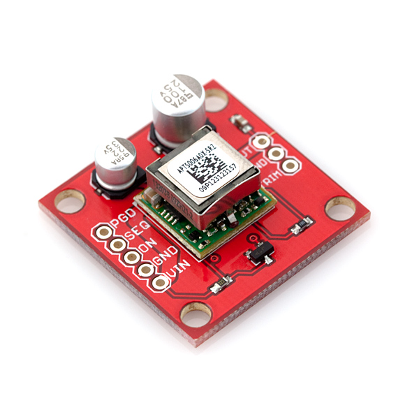
This is a breakout board for our non-isolated, 6A DC-to-DC Converter Module. The module can convert any DC voltage between 4.5-14VDC to a selectable voltage between 0.59 and 5.5VDC.
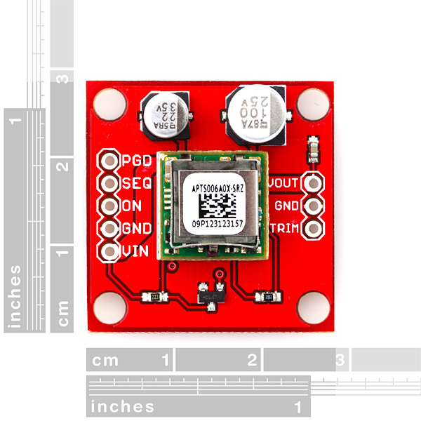
To set the output voltage to the desired level, a resistor must be added between the Trim and GND pins. For example, to set the module to output 5V use a 1.34kΩ resistor, or to get 3.3V use a 2.182kΩ. See table 1 in the module's datasheet for more resistor values.
The ON/OFF pin on the board can be pulled high to turn the converter module on and low to turn it off.
Board comes as shown, with all components (aside from the trim resistor) populated. Access to all pins of the converter module is provided by two, 0.1" pitch headers.
- 4.5-14V Input voltage
- 0.59V-5.5VDC Regulated output
- 6A max output current
- Low output ripple and noise
- -40C to 85C operating temperatures
- All pins of converter module broken out to 0.1" headers
SparkFun DC/DC Converter Breakout Product Help and Resources
Core Skill: Soldering
This skill defines how difficult the soldering is on a particular product. It might be a couple simple solder joints, or require special reflow tools.
Skill Level: Noob - Some basic soldering is required, but it is limited to a just a few pins, basic through-hole soldering, and couple (if any) polarized components. A basic soldering iron is all you should need.
See all skill levels
Core Skill: Electrical Prototyping
If it requires power, you need to know how much, what all the pins do, and how to hook it up. You may need to reference datasheets, schematics, and know the ins and outs of electronics.
Skill Level: Competent - You will be required to reference a datasheet or schematic to know how to use a component. Your knowledge of a datasheet will only require basic features like power requirements, pinouts, or communications type. Also, you may need a power supply that?s greater than 12V or more than 1A worth of current.
See all skill levels
Comments
Looking for answers to technical questions?
We welcome your comments and suggestions below. However, if you are looking for solutions to technical questions please see our Technical Assistance page.
Customer Reviews
4.8 out of 5
Based on 4 ratings:
2 of 2 found this helpful:
Awesome value!
Bought this little board to use for project testing and it has become very invaluable to me now. It is easily breadboardable and works excellent! I recommend this to anyone doing electronics design!
Very Handy Device
I bought this DC/DC converter to use in my plating experiments because I need a controlled voltage around 1 volt. I can use a 6v or 12v battery and dial in the voltage I need. It's so much more efficient than a voltage regulator that just burns off excess power and when your power source is a battery, that is very important. In addition, I can also use it as a benchtop power supply when working on circuits for my robot projects and, if needed, I could charge a USB device from a 12v battery.
It works as advertised and I'm greatful
I've been looking for something to drive herds of LEDs for portable lighting and giant clock digits. If you are going to drive this much past 3-3.5 amps, a heat sink against the square metal hybrid case is a good idea. I'm looking forward to applying this little item in some other high current applications.
The board is clearly labeled, logically laid out, thick, plated through, with construction and engineering that shows that Sparkfun knows what it's doing. So far, the guide and data sheet have allowed me to easily apply this converter to an Arduino driving ravenous LEDs.
The resistor values called for in the data sheet for the various voltages are precise. There is ample room on the back of the board to chain a couple of them together to get close to the desired value for your voltage.
If you need a higher than average current buck converter. This part is definitely recommended.
Very useful
I have found this power-converter very useful for driving 5V devices that require a lot of current, such as a Raspberry Pi with attached spinning disks, off 12V lead-acid batteries, that work as an UPS of sorts. The efficiency is good, and it Just Works.
With two 2.7 kiloOhms 1% resistors in parallell between TRIM and GND, this becomes. 1.35 kiloOhms and makes the regulator output 5 V.
Only caveat is the ON input really, since this drives the gate of a logic-level NMOS transistor, the voltage here shouldn't be much more than about 5 V. I used a 4.7V zener diode and a resistor to limit the voltage here.
On the other hand, when I have wanted to have a mechanism for shutting off the power, delayed after the Raspberry Pi has sent out a "shutdown request" to a separate microcontroller, having a secondary low-power 5V standby supply for this, via an LM78L05, this on/off control works great. Since the microcontroller that I use has several analog inputs, I use it for supervising various other voltages in the vicinity.
I am trying to output 5V with various input voltages (6V, 7V, 8V, 9V, 10V, etc). How should I choose a Rtune and a Ctune for each specific case?
Help is much appreciated!
So does this device take say 5v 2A power adapter and turn it into a 5v 6A power adapter or am I missing something?
Nope, this will turn a 12V 3A supply into a 5V 6A supply though. It is basically a voltage regulator that changes the output voltage. But it doesn't create power. If your supply is only putting in 10W, you are only going to get 10W out (assuming 100% efficiency, in reality you'll get a little less).
The 6A load requires active cooling. Keep it below 3A or it'll burn out & fry your gadget.
How hot do these get? I'm looking to go from 12V to 5V @ maybe 100-200mA. I don't see anything in the data sheet. I don't see how a heatsink could be attached. I was going to use a 7805 with a heatsink in my project, but it's turning out to be just a little to big for the space I have to play with. If this needs a heatsink, or some extra room for airflow, then it might defeat the purpose of using instead of the 7805.
With 380mA. mine is 122-133F measured by IR. It is stable and doesn't seem to need a heatsink.
Any Idea of how much current goes through Rtrim? I couldn't find it in the datasheet.
could i use 5 of them in parallel? i want to power a bunch of high amp LEDs via a TLC5940 led driver.
i guess i am asking because the datasheet mentions something about Mhz. I am wondering if the switching frequency of this converter would possible be visible in the LEDs.
For anyone wondering, since it took LOTS of digging into the datasheet to find this, this is a STEP DOWN module, and the dropout according to the datasheet is 1V. In other words, the output you set the module for must be at least 1V lower than the input you give it.
For this price I expected a trimming potentiometer to set the output voltage to be on the board.
wow, it's good for me
Why not use the non inverting power on signal version and omit the n channel MOSFET?
Could something like this be used to power up a Raspberry Pi from Li-Ion batteries?
Yes, in much the same way a nuclear reactor can power a light bulb.
Connecting the On/Off to VIN, the datasheet has a 20K pull up resistor on it. Does the spark fun PCB have this resistor on it or do I have to put one in. The specifications say just add the trim resistor (1.3K). Thought I better ask before its too late. Has anyone connected VIN to On/Off without the resistor and blown it up!
There is no name of the dc-dc converter but i will not buy this as long as i can make it myself and this one is so expensive.
There's a link to the module's datasheet in the documents section.
Can i use this for getting 5.2V from 4.9V 2a?
Nope, sorry. This guy only lowers voltages.
I can't seem to find the EAGLE footprint file for this in the Sparkfun libraries, and tried to make it myself. But I can't seem to find the mechanical drawings to do the footprint, either? Did I miss something?
Maybe my expectations are too high for a $30 board, but as an amateur I'm not sure when I'm looking at a schematic for the DC-DC converter module itself or when I'm looking at the schematic for the breakout board. Does anyone have any sample circuits using this? I'm specifically looking to drop down to 5V, but unclear about the use of all the pinouts.
Many of our breakout board products require looking at both the datasheet for the part, and the schematic for the board, to figure out how to wire everything up. We know this can be daunting for a beginner, but you can always ask questions (techsupport at sparkfun.com) and we'll be happy to help you out. Here are the basics for this board:
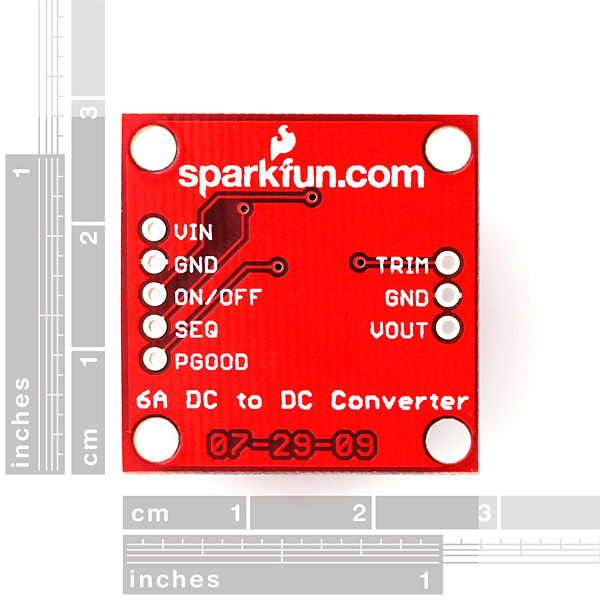
VIN - connect this to your input voltage
VOUT - this will be your output
GND - common ground (connect to both input and output grounds)
TRIM - connect via resistor to ground (selects output voltage). According to the datasheet on page 14, this resistor should be 1.34K for 5V output. You can select a value that is close to this (1.3K or 1.5K), or use a 10K potentiometer to dial it in exactly.
ON - connect to VIN to turn on, connect to GND to turn off
I hope this helps, good luck with your project!
I connected ON to VIN - magic smoke came out? BAD ADVICE!
Very sorry to hear that! But if you check the datasheet, you'll see that this is the correct way to operate the part. Contact our Technical Support department and they'll help figure out what went wrong.
What's the conversion efficiency of this module?
how about a eagle footprint of the breakout board?
I bought one of these heatsinks to use with this: http://www.radioshack.com/product/index.jsp?productId=2102857. Obviously, it wasn't designed to be used with this regulator; it won't cover the entire thing. If I buy another heatsink, can I affix two of them side by side (with thermal compound) to the converter module?
do you sell a heatsink for this product?
People hi have a question...
I need a linear 5v and 2A...
I have a NiMh Battery of 7,2v and 3A..
I can use this board to make an Output of 5v and 2A??
Thanks,
André.
Yes. Note that Amps is determined by the draw of whatever you are powering. Because you are going down in voltage, you don't have to worry about the current rating of your battery too much.
See the forum for further discussion on your particular case;
http://forum.sparkfun.com/viewtopic.php?f=14&t=29406
I wish to drop 12V to 3.3V and plan to use this converter with a 2.2kΩ resistor between trim and ground.
Q: Can this resistor be 1/4W? Or does it need to be something with a higher W rating?
Thanks!
A: 1/4W is fine - check the datasheet, one use case is dropping 12V to 1.8V @ 4.5A max, and they suggest all the way down to a 0603 package.. those are typically rated for 1/16th of a Watt :)
What is the dropout voltage of this module? For instance, if it is set for 5.0V output, can I get 6A out with a 6.0V input? This information is notably absent from the datasheet!
I accidentally gave 5V input while having set resistors for 5V output: I got some 4.4V output, so, if your 6V source does not drop voltage when sourcing some amps... you're ok.
I've to praise again this unit. It resisted some minutes of short-circuiting the output. It is working in a humid and dusty environment. Under 3A output, no active cooling is needed (you will see it hot when asking for some 2A, anyway).
This unit is also smaller and cheaper than a Digikey 3A-rated one (which only features input "up to 18V").
Can we get a respin of this board with the new COM-10613 digital Potentiometer on the trim pin?
I don't agree with Robert that this would be a good idea. What does a digital potentiometer offer that you don't get with a common trimming potentiometer. The latter only needs a small screwdriver to set the output voltage, the former needs a microcontroller and a program for it.
Hum, that's a good idea.
Could I use this with http://www.sparkfun.com/products/8484 to charge an iPad at 5v - 2.1A ?
What is the function for SEQ and PGD?
If you don't know what are PGD, SEQ and ON/OFF pins (power good status, voltage sequencing, remote on/off control), you may safely leave them unconnected. More info in the datasheet.
To get an exact 5.00 volts you have to find out a 1340 ohm resistor. I lined up in series three spare resistors (summing some 1337 ohm) and it went quite near to exact 5V.
You may measure your spare resistors and then apply the formula:
5.91 / (value in kiloOhm) + 0.591
to estimate output voltage before soldering them.
Remember that high loads require thicker cables.
This DC/DC is small, silent and powerful. Anyway, I have some suggestions for next release:
- another GND hole near to TRIM
- another VIN and another GND on the side below (the one without components).
I am planning on using this for a 5V supply from my car, for a carcomp. Is there anything I need to do to protect against spikes on the 12V from alternator &etc? thanks.
You will probably be fine. Do a search in the data sheet for transient response. Starting on page 6, it looks like you probably won't have more than a few tens of mV during strong input voltage transients. Most micros will still operate at 5.3 volts, which is 300 mV spike.
You can also tune the feedback loop if you really want to. I'm using it in an automotive environment. I will put decoupling caps on my 5- and 12-volt rails (Cin and Cout, page 1). That's all I will do for transients. I'm not otherwise worried.
how about a second gnd next to the trim?
Yes! Wish it had come two weeks sooner so I wouldn't have ordered a bunch of parts to bodge a supply together, but better late than never.
From the description and the datasheet it looks like it is fine to tie the on/off to the input voltage to turn it on? Pullup resistor required?
The data sheet Fig. 42 shows what the enable circuitry looks like internally. I would agree that it looks like it is fine to tie the on/off to Vin and turn it on.
Well, that was terrible advice. MY device just let it's magic smoke out. THANKS.
It's not other people's fault if you don't do due diligence.
Look at the schematic. ON is connected to a MOSFET. Connecting anything higher than 5V will surely let the smoke out. This needs a HIGH or LOW signal, not VIN.