- Home
- Product Categories
- Audio Connectors
- MIDI Connector - Female Right Angle

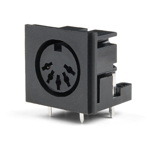
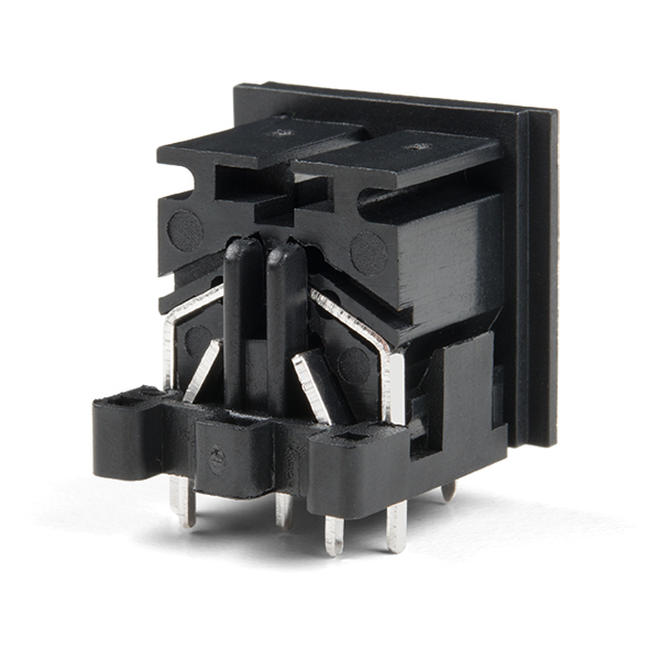
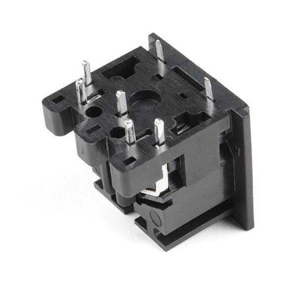
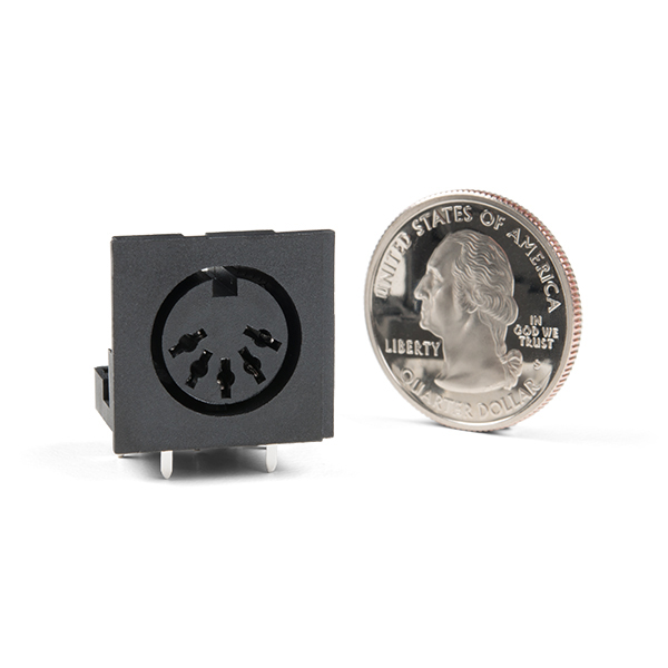
MIDI Connector - Female Right Angle
Looking to add MIDI to your project? This is a female, 5-pin, right-angle DIN 5/180? connector which will interface with most standard MIDI cables.
The pins are spaced by just about 0.1", making these connectors easy to prototype with. The contacts are rated to 2A @100VAC and 1A @ 24VDC.
Keep an eye out for upcoming MIDI-based products using these connectors!
MIDI Connector - Female Right Angle Product Help and Resources
Hackers in Residence - The ElectricBone
June 25, 2014
Drum machines and keyboards have been the standard for making digital music, but how do you make electronic music if you're trained to play the trombone? One of our Hackers in Residence, Carlos Mello, took it upon himself to find a solution to that very question.
Core Skill: Soldering
This skill defines how difficult the soldering is on a particular product. It might be a couple simple solder joints, or require special reflow tools.
Skill Level: Noob - Some basic soldering is required, but it is limited to a just a few pins, basic through-hole soldering, and couple (if any) polarized components. A basic soldering iron is all you should need.
See all skill levels
Comments
Looking for answers to technical questions?
We welcome your comments and suggestions below. However, if you are looking for solutions to technical questions please see our Technical Assistance page.
Customer Reviews
4 out of 5
Based on 1 ratings:
It's exactly what it seems like
Put it on a protoboard and rip out your circuit. Find the pinout and solder. Simple as it gets. This is the same part I replaced in a production midi drum set. It's "the part that gets used" as it were.
The Eagle package for this part is wrong. All the pins are mislabeled. Looking at the datasheet, the pins from left to right order are: 3, 5, 2, 4, 1. On your Eagle DIN_5_FEMALE_SUPPORT package the order is: 2, 4, 1, 5, 3. Github pull request: https://github.com/sparkfun/SparkFun-Eagle-Libraries/pull/22
Do these pins fit into a breadboard!? Also, concerning the 2 pins located at the front, do they serve only for mounting purposes?? Do they have to be connected to GND or NC (the front pins). I take it that there is a possibility they may interfere with plugging into a breadboard. I imagine you can plug it into the Middle of the boardboard so that the mounting pins fit into the other section of the breadboard apart from the other section.
Looking forward to answers.
-Michael B
What would be the easiest way to get this mounted in a panel? Somehow bolt the circuit board to the side?
Ah, I'll use the little right angle brackets you guys have. Those should work well.
What pins do I solder to for MIDI?
It depends on whether you're working on MIDI IN, or MIDI OUT/THRU.
MIDI Out and thru get pin 2 soldered to ground. Do NOT solder pin 2 to ground for MIDI IN. It needs to float or else you'll get a noisy ground loop.
Schematic and my own OSH board design here: http://10rem.net/blog/2012/03/13/designing-the-open-source-hardware-net-gadgeteer-midi-module
Eagle part, please!
Nvrmnd. Made one myself.