- Home
- Product Categories
- Temperature
- Infrared Thermometer - MLX90614

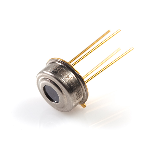
Melexis' MLX90614ESF-BAA is an infrared thermometer designed for non-contact temperature sensing. An internal 17-bit ADC and a powerful DSP contribute to the MLX90614's high accuracy and resolution. It has a huge number of applications including body temperature measurement and movement detection.
The MLX90614 provides two methods of output: PWM and SMBus (i.e. TWI, I2C). The 10-bit PWM output provides a resolution of 0.14°C, while the TWI interface has a resolution of 0.02°C. The MLX90614 is factory calibrated in wide temperature ranges: -40 to 85°C for the ambient temperature and -70 to 382.2°C for the object temperature. The measured value is the average temperature of all objects in the Field Of View of the sensor. The MLX90614 offers a standard accuracy of 0.5°C around room temperatures.
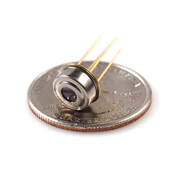
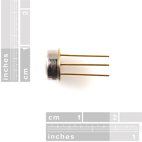
This device comes in an industry standard TO-39 package. We're carrying the 3V version of this sensor.
- Small size, low cost
- Easy to integrate
- Factory calibrated in wide temperature range:
- -40 to +85°C for sensor temperature
- -70 to +380°C for object temperature
- SMBus compatible digital interface
- Customizable PWM output for continuous reading
- High accuracy of 0.5°C over wide temperature range (0 to +50°C for both Ta and To)
- Measurement resolution of 0.02°C
- Single and dual zone versions
- Simple adaptation for 8 to 16V applications
- Power saving mode
- Different package options for applications and measurements versatility
- Automotive grade
Infrared Thermometer - MLX90614 Product Help and Resources
MLX90614 IR Thermometer Hookup Guide
October 29, 2015
How to use the MLX90614 or our SparkFun IR Thermometer Evaluation Board to take temperatures remotely, over short distances.
Core Skill: Programming
If a board needs code or communicates somehow, you're going to need to know how to program or interface with it. The programming skill is all about communication and code.
Skill Level: Competent - The toolchain for programming is a bit more complex and will examples may not be explicitly provided for you. You will be required to have a fundamental knowledge of programming and be required to provide your own code. You may need to modify existing libraries or code to work with your specific hardware. Sensor and hardware interfaces will be SPI or I2C.
See all skill levels
Core Skill: Electrical Prototyping
If it requires power, you need to know how much, what all the pins do, and how to hook it up. You may need to reference datasheets, schematics, and know the ins and outs of electronics.
Skill Level: Competent - You will be required to reference a datasheet or schematic to know how to use a component. Your knowledge of a datasheet will only require basic features like power requirements, pinouts, or communications type. Also, you may need a power supply that?s greater than 12V or more than 1A worth of current.
See all skill levels
Comments
Looking for answers to technical questions?
We welcome your comments and suggestions below. However, if you are looking for solutions to technical questions please see our Technical Assistance page.
Customer Reviews
4.8 out of 5
Based on 5 ratings:
4 of 4 found this helpful:
Remarkably easy to use and accurate
I was able to get readings from the sensor over I2C in the course of a day and was able to confirm its accuracy with an ice cube and boiling water. I'm adding a Fresnel lens so it can measure temperature accurately from a distance. Gonna have a lot of fun with this little guy!
1 of 1 found this helpful:
Exactly what I needed
Wide temperature range, steady output under steady temperature conditions, and surprisingly resistant to spilling soda on the lense. Repeatedly.
1 of 1 found this helpful:
Worked right out of the box.
Does exactly what it says on the tin.
Be aware that this is a 3v device, and not suitable for use with 5v Arduinos.
Also, the imaging angle is rather wide - make sure to account for that in your application.
Easy to set up but I wish ...
I found setup to be very easy using Sparkfun's guides. On my arduino board, finding a source for 3.3v wasn't easy. I still have to make adjustments to calibrate the values to improve accuracy, and figure out the field of view and distance issues. But it was very rewarding to just wire it up, upload the sketch, and immediately get intuitive values.
If I had to do it over, I would get the eval board with the built in arduino, but that was out of stock at my time of purchase. It's a good looking board and results in a much more attractive project setup than my mess of wires.
My use case is to identify people whose body temperature exceed the norm. My MLX90614 sits on top of a webcam mounted to a pan tilt rig. I wish the board also included a laser to validate the exact surface it was measuring.
MLX90614 works as advertised
The Sparkfun tutorials on this product have been helpful and got me up and running in no time.
This sensor works fine. used it with raspberry pi for digital contact less thermometer.
I found this youtube video useful for reading the sensor value.
Reading MLX90614 in raspberry pi using python
I would like to buy this Thermonemeter.
Anyone know how far away the object must be from the sensor to get an accurate measurement?
Data sheet says sensor is "Dual Zone". How do I get separate readings for the two zones?
FYI, The hookup guide is wrong when it says that the power supply is in the range of 3.6V and 5.0V, if you look at the datasheet for the 3V-TO-39 package it actually says that the range is 2.6V to 3.6V which may be good news for most.
Anyone notice the mistranslation in the datasheet.
I consider using MLX90614AAA to measure temperature within car compartment, but I am
embarrassed about the Sun light that may hit the module. Is it a significant issue?
Special care is taken to cut off the visible light spectra as well as the NIR (near IR) before
According to the datasheet: "An optical filter (long-wave pass) that cuts off the visible and near infra-red radiant flux is integrated in the package to provide ambient and sunlight immunity. The wavelength pass band of this optical filter is from 5.5 till 14μm (except for xCH and xCI type of devices which incorporate uncoated germanium lens)."
I have not looked at the spec sheet to see what material is used for the window. It looks identical to the silicon used in the Melexis thermopiles I used to use for an attitude sensor of my first autopilot sold back in 2008. If it is in fact silicon, then it acts as a band pass filter with SHARP cutoff for all wavelengths below about 1050 nm. Without being rigorous here, we know the sun looks orange/yellow so I'd assume the dominant photon wavelength is around 600nm... with plenty in the red, and less in the blue end. So again if window is silicon, this means NONE of the visible nor half of the NIR even make it into the sensor. All that can get through is NIR longer than 1050 nm as well as all the FIR. Check out http://www.flickr.com/photos/imager/3380554807/
Also, then sun is very tiny in the sky relative to the total field of view of these sensors: sun = 0.5 degrees, sensor field of view is > 90 degrees. By ratio of area of those disk sizes, this means the sun is basically NOTHING. So, sun = tiny, and sensor can't even see the dominant wavelengths of the sun.
My autopilot product used an array of 6 of these sensors pointing 1 each up/down left/right and forward/backward to "see" the thermal difference between sky and earth. Blue sky looks very cold as in what it is in the stratosphere up where passenger jets fly (let' say -60 centrigrade). Even if it's overcast with low clouds, those clouds are most certainly going to be colder than the ground. So these sensors with their large FOVs can be used to calculate tilt angles of the UAV relative to the horizon... and it is surprisingly accurate on the order of 1 to 2 degrees of angle. Where I'm going with this is that even here in Phoenix Arizona during a heat wave in 2008 with stark blue sky and full bright sun, the UAV autopilot was still rock solid (as always) measuring tilt of the UAV and flights were perfect.
I wouldn't at all fear trusting these sensors outside during a sunny day.
If the sun doesn't make a difference because it's such a small solid angle of the sky, how come it warms me when step into it from the shade? It may be a small part, but the radiative transfer depends on the cube of the temperature difference, so a small portion of the sky at 5000 Kelvin can overwhelm the effect of a colder sky much closer to the ambient temperature. Please see page 40 of the datasheet about sunlight. Visible light from the sun, as well as near infrared and ultraviolet, can heat the whole package, changing the temperature-difference between the thermopile and the ambient sensor, thus changing the reported temperature. The wavelength argument is much more reasonable, even though it also has limitations, than the solid-angle argument. I'd stick to that. It's interesting to think about which applications will depend on shielding from sunlight and which won't—Thanks for reporting on use avionics. I agree that pointing an infrared bolometer at the sky is interesting—It's so cold, even on a hot summer day, if clear. Of course cold isn't a thing, it's the absence of warming radiation, an absence natural to expect from space.
Nice sensor.
Here is an Arduino Sketch that lights it up:
(Adapted from Pololu's Board)
Since I use 4&5 for signal, the next pins 2&3 can be used for power.
#include
static void nunchuck_setpowerpins()
{
#define pwrpin PORTC3
#define gndpin PORTC2
DDRC |= _BV(pwrpin) | _BV(gndpin);
PORTC &=~ _BV(gndpin);
PORTC |= _BV(pwrpin);
delay(100); // wait for things to stabilize
}
void i2c_start() {
TWCR = (1 << TWINT) | (1 << TWSTA) | (1 << TWEN); // send start condition
while (!(TWCR & (1 << TWINT)));
}
void i2c_write_byte(char byte) {
TWDR = byte;
TWCR = (1 << TWINT) | (1 << TWEN); // start address transmission
while (!(TWCR & (1 << TWINT)));
}
char i2c_read_byte() {
TWCR = (1 << TWINT) | (1 << TWEA) | (1 << TWEN); // start data reception, transmit ACK
while (!(TWCR & (1 << TWINT)));
return TWDR;
}
void i2c_receive_pec() {
TWCR = (1 << TWINT) | (1 << TWEN); // start PEC reception, transmit NACK
while (!(TWCR & (1 << TWINT)));
}
void i2c_stop() {
TWCR = (1 << TWINT) | (1 << TWSTO) | (1 << TWEN); // send stop condition
}
//Returns 100 times the temperature read by the sensor giving a 0.01 degree resolution.
long i2c_read_temperature_f() {
long low_byte, high_byte;
//DDRC = 0; // all inputs
// PORTC = (1 << PORTC4) | (1 << PORTC5); // enable pull-ups on SDA and SCL, respectively
TWSR = 0; // clear bit-rate prescale bits
TWBR = 192; // produces an SCL frequency of 50 kHz with a 20 MHz CPU clock speed.
i2c_start();
// The expected value of TWSR & 0xF8 is now 0x08 (Start condition transmitted).
Hi ben121, i wanted to ask you if you are willing to donate this code to bildr.org?.
I want to add it to the wiki, http://wiki.bildr.org/index.php/Infrared_Thermometer_-_MLX90614
It could be very useful for people trying to use this component?
The community thanks you!
This is way easier to implement (code) with the IOIO board.
http://demos-ioio-irthermometer.blogspot.com/
http://youtu.be/3GkSte5QZ0g
Doh! Wrong command - should be 0x2E not 0x2D ! 24 hours wasted.
If this was a really intelligent sensor, it would have known what I meant.
Hi JonT,
does it work fine ? Can you send me the fully code for the changing address of a mlx90614?
For this code I have to connect only one per one mlx, after this setup code with changing the address, the address is permanent, or only during the same session ?
thanks in regard
IR, oh what fun it is. I use the little handheld IR non-contact thermometers in my work. I now have an infrared camera, and learned a lot more. What range will they work? Forever. The catch is it takes an average of what it sees. A small apparent size will not be detected. If your target fills most of the Field Of View, you are measuring your target. Will it see thru glass? No, infrared reflects off of glass like a mirror. My camera can see someone standing behind me. My camera is sensitive and can even see warn foot prints on the floor. Will it give an accurate temperature reading of shinny surfaces? No, aluminum foil (flex duct and the like) reflects infrared the temperature of things around it. It will not see the temperature of air, but the things the air hits will give hints of the air temperature striking the objects. And have you heard of emissivity? Some things look like the temperature they are and others look like they are colder. On average they work well, but infrared is a very different color of light and somethings will surprise you.
I really wanted to use this sensor with a Teensy 3.0 (ARM based) board, but all the working code I could find uses the i2cmaster library and is dependent on the microcontroller being AVR based. I never used I2C before this project so I still can't get it to run in PWM mode, but I did manage to get the sensor to communicate successfully using Wire.h included in Arduino 1.0.5 and print a readable temperature using some code from the bildr tutorial. I hope this will be of help to someone. #include Wire.h #define LED_pin 13 #define slaveAddress 0x00
Here is a functioning copy of your code, some parts got deleted. Works with Teensy 3.1
No, your it's not! You cannot have a Wire.beginTransmission in setup like this!!! The code of Kammi it's correct, just need to include wire.h and define the slaveAddress.
I know it states that it is factory calibrated, can it be re-calibrated for a wider temp range with a lower resolution?
Wondering if these could be used for cloud detection, by measuring the sky's ambient temperature? Not sure what distance range these things are able to measure up to? :)
Yes, it should work fine. Since you will be pointing the sensor upwards towards the sky you will want to protect it somehow from rain/dirt/etc.
You could use a germanium window, but that is a bit costly. A window made of thin plastic wrap will keep moisture and dirt from falling on the sensor while being essentially transparent to the infrared. It will not be as durable as the germanium window however.
Does anyone know what the range is?
Thanks
Hi Dave. I posted my problem on this component to the Sparkfun Forum weeks ago and never got one reply. I've also tired to point out to Sparkfun that they'd do more to build business by spending time to properly support what they sell (like this component) then compare their web logs to Arduino and give away $100k worth of stuff. But this old codger's words have fallen on deaf (young) ears. Sparkfun--it must be a fun place to work! Guess I'm just jealous :)
"measurement" is misspelled as "measurment" in the description.
About the MLX90614 I have it up and running, but I'm kind of stuck. I'm trying to measure the infrared radiation in watts and no the temperature. Do you think this is possible with this device?, I have been checking the library code, but as I said, I'm stuck. Any advice and suggestions will be greatly appreciate
We've struggled quite a bit to establish communication between an Arduino UNO and MLX90614AAA using the Wire Library for I2C. We finally got it running though. Here's the sketch!
Hello, I want to use this sensor (3V input) with the MicroView (5V output). I know is a totally noob question, but... any clue on How can I do that?
Thank you very much.
Hello everyone, i have one question, and i need change emissivity to 0X04 but i don't know how to do. Someone could help me PLEASE !
I assembled a prototype for kirlian photography using this sensor and Arduino. I was able to read the temperature in the serial console and used the Java software for visualization from http://blog.arduino.cc/2012/10/25/diy-less-expensive-thermal-imaging-camera/
Unfortunately, the results are not as clean as I expected. I see a big blob of colors rather than object silhouette. Is there any specific distance for this sensor to get optimal results?
Hi, I am searching for a detailed information of the intern calculation of the object-temperature, as it is explained for the mlx90620 for example... But in the datasheet isn't even a complete Information about the RAM-register... Has anybody some Information for me (exept the Stefan-Boltzmann-law)?
Hi, I want to ask that this sensor able to detect body temperature or not? and how far a person away from the sensor can be detected?
This is way easier to implement (code) with the IOIO board.
http://demos-ioio-irthermometer.blogspot.com/
http://youtu.be/3GkSte5QZ0g
Hi,
I want to ask from which distance you can measure the temperature with the MLX90614 sensor. I am looking for a sensor which can dynamically measure the temperature from surfaces in a distance of 0 to 20 meters with an Arduino.
Thanks
I purchased one of these about 3 months ago. I got it running with the I2C (TWI) interface in 20 minutes. However, I worked for almost 3 months looking for information on running this with its PWM interface. First the AVR135 documentationand code from Atmel on using timer capture to measure PWM duty cycle did not work on a port to the UNO. I worked almost 2 months to get the UNO to reliably return a PWM duty cycle. Once I got that working I found in the MLX documentation that pin 2 is for both SDA and PWM. I need pin 2 to set the MLX to PWM which is done on analog pin 4 in the TWI mode. Then, because the only pin which can be used to read the PWM is digital pin 8 on the Arduino UNO, I needed to buy another Arduino UNO and set it up to read the PWM encoded data off of the MLX pin 2. I am looking to see if anyone else has attempted this. I am looking at doing either a physical switch or maybe an electronic relay to physically reconfigure the MLX connections to the Arduino. I would like to have the code set the system to a TWI physical configuration for setting the operation mode of the MLX and reading temp if it has been set in the SMB mode and to reconfigure the physical connections from the code to read temp from pin 8 if the MLX is set to the PWM mode. I am not looking for a cost effective solution. I am just looking to have fun and work on something (as far as I can see) no one else has done in any other project.
dear lord, let go of the arduino! the second you start running out of pins don't just use another uno, get an ATmega644 or similar, or even a PIC, and program it in C!! It's so easy. You're making it way hard on yourself.
So if I want to use this to measure temperature, but cannot seem to build it in a lab, how would I go about that. Today I set up a scope and power supply and the like to power this on, and nothing worked. I was unable to see anything on the output, trying multiple ways to do this, and got nothing. Some research shows I should add resistors. I am using this to measure hot and cold at a distance, not very far, and tying in with distance sensors to create a object avoidance style robot. Thank you for your help!!!
I used this with a PIC microcontroller but the hardware hook up should be the same for arduino.
There are two modes that this sensor works in. You can use it in PWM mode or I2C. I2C is the preferred method. You decide on the mode by address the sensor, so by default it's ready to go in I2C mode.
The sensor has 4 pins. The VSS (Ground), VDD (+5v), SDA (Data), and SCL (Clock). When using the sensor in PWM mode, SDA becomes PWM, and SCL becomes VZ.
You need to connect VSS to ground and VDD to +5 vdc. Be sure to use a filtering cap on the power pins of the sensor (0.1uF).
SDA and SCL need pull up resistor, a value of about 2.2k should work. If you leave them floating, (no pull up resistor), your data will be corrupt.
Code is provided above for arduino so I wont go too in-depth into the process but generally what your doing is using a modified I2C Bus, sending out the devices address to read from, then processing the data and doing something with it.
The device can return two values. It can return the target temperature, that is the temp the IR sees, and it can return the devices internal temp. This extra value, the devices temp, is handy when offsetting for ambient temperatures.
You will not be able to see a voltage on your scope like with an LM34/35, this sensor is much more sophisticated and therefore, harder to setup. But ones everything is setup.. it really is easy to use
This part is now available in the Upverter library here.
Note that the datasheet specifies that the optical filter has a wavelength bandpass of 5.5um to 14um. Glass is opaque for near IR wavelengths longer than ~2-4um, so this product will not measure temperature through glass.
Just something to keep in mind if you were thinking about using a lens.
what is range of this device, as in how far away can the object that I want to measure be?
http://mbed.org/users/4180_1/notebook/mlx90614-i2c-infrared-thermometer/ has a code example for mbed.
Just for those interested in testing quickly MLX90614 with I2C, I have wrote a tutorial on Dangerous Prototypes with BusPirate 3.x
See the link here http://dangerousprototypes.com/forum/viewtopic.php?f=28&t=2936
Best Regards
Benjamin
I realize that this an old post, but would you happen to know the command string to put the sensor into PWM mode?
Is it possible to offer the following models below:
MLX90614ESFAAF
or
MLX90614KSFAAF
or
MLX90614ESFAAI
or
MLX90614KSFAAI
Can this device output data in Watts/cm2 instead of Celsius ? My goal is to hit it with a laser and read out laser power.
Will the lens from a CD drive laser assembly work as a lens for the MLX90614 ?
If people need help using this sensor LabJack has a nice AppNote that can help you understand how to use this sensor.
http://labjack.com/support/app-notes/mlx90614-ir-temperature-sensor-i2c
http://search.digikey.com/scripts/DkSearch/dksus.dll?Detail&name=MLX90614ESF-ACF-ND
This is where you can buy the version of this sensor with a 10 Degree field of view, as opposed to this one's wide field of view.
Does anyone know which material is the extra housing of the smaller Field of View sensors.
The 35 deg FOV sensors have an extra housing on top of the 90 deg FOV, but i simply cannot find what it is made of.
Thanks
The module measures infared light in a 30 degree field of view, it then delivers the average as the sensed temperature.
The 10 FOV temperature gradient compensated is on EBAY
http://cgi.ebay.com/ws/eBayISAPI.dll?ViewItem&item=320707891927
but it costs a bit more because of the compensation and the lens needed for a small FOV. I plan to use one for a project where I need a narrow FOV.
Yes, you cab detect water, if it is different from the temperature sensed, and it will almost always be. You might be better off with a simple $1 set of infared diodes though.
It should be able to detect another robot because the robot should be hotter than the environment. A lot will depend on the detection code you write.
I was woumdering if anyone could explain to me exactly what this does and how a person is able to perceive the information given by the sensor.
The module measures infared light in a 30 degree field of view, it then delivers the average as the sensed temperature.
By the way, do you know what means the data_low and data_high variables?, For example I got:
Data Low: 90 Data High: 59 Kelvin: 303.87 Celcius: 30.72 Fahrenheit: 87.30
Does anybody know if this would work well with a small body of water, possibly flowing water?
It would see the water as a different temperature, so it would. The problem is it doesn't why the temperature is different so depending on the use it might be confused by say white paint on asphalt, or dark gravel on snow etc.
What is the maximum voltage for the I/O pins?
I've noticed that it must be supplied with 3,3V,
but is it possible to hook it directly to the SMBus witch varies between 0-5V?
No. the maximum is 3.6v. You need the mlx90614esf-aaa for 5v 30' FOV
I was somewhat surprised to have this shipped without any antistatic precautions.
Hopefully it's come to no harm inside of the small cardboard box it was shipped in, but given that it's not a cheap part I'd expect more care.
I'm trying this code http://interface.khm.de/index.php/lab/experiments/infrared-thermometer-mlx90614/ on a Mega. I connected to pins 20/21 instead of 4/5, but everything I try results in hanging up in i2c_start_wait, because the status returned is TW_MT_DATA_NACK; causing it to think it is busy and starting over.
I've tried pull ups on the SDA/SCL. Any other suggestions?
Thanks to all of the folks that posted here. I used this neat component as the sensor to control the temperature of a reflow soldering hotplate using an Arduino and a sketch I wrote based on info I got from posts here. The details are too long to post here but I wrote up the whole thing on my site and wanted to pass along a link:
http://www.ayefon.com/reflow
I'm getting SUPERB SMT soldering results using this rig and this is the first time I've ever done SMT work. This little IR thermometer is just the ticket. Feel free to write me if you have any questions I haven't covered in the writeup and code posted on my site (don at ayefon.com)
wow, andruino seems complicated. with picaxe, I have a 20x2 and with 4 lines I was able to get data off it.
hi2csetup i2cmaster, %10110100, i2cslow, i2cbyte
pause 10
hi2cin $07, (b0,b1)
pause 10
Two questions:
1) In PWM mode, could a low-pass filter be used in conjunction with a PIC ADC to read the temperature? Accuracy to within 1 degree F is acceptable for my intended application.
2) Is there any way to have it power up without programming in PWM mode?
Thanks in advance. Glad to see SparkFun carrying this, although would like to see the 5V option.
Are these single or dual zone or gradient compensated? Also is the FOV 10 or 35?
Singe, no, 30.
Oh, FAIL! Ben121's code has a problem. Unless you specify otherwise, character values are signed in C. i2c_read_byte returns a char, which is signed. So values between 0x00 and 0x7f go from 0 to 127, and 0x80 through 0xFF go from -128 to -1. The fix is simple: change the type of i2c_read_byte from char to unsigned char. Also, because it could affect calculations, change the type of the argument to i2c_write_byte to unsigned char as well.
Argh. After extensive testing, the chip seems to be not working reliably with Ben121's code on the Teensy. I can get a temperature some times, but other times I'm getting some different value. It surely looks like a timing problem on the I2C bus, like maybe I'm using the wrong clock phase or something. Anybody seen this?
I'm battling to cahgne the address of the sensor (I want to use two on the same bus). I have it hooked up to an Arduino Duodecimila, and I have Dave Eaton's code working fine. I seem to be able to write to the EEPROM OK but the address does not change (even after a power down). Here is the code:
// Now change address. First erase
i2c_start_wait(dev+I2C_WRITE); //send start condition and write bit
i2c_write(0x2D); //send command for device to return address
i2c_write(0x00); // send low byte zero to erase
i2c_write(0x00); //send high byte zero to erase
i2c_write(0x6F); // send PEC
i2c_stop(); //Release bus, end transaction
delay(100); // then wait 10ms
// Then write new address
i2c_start_wait(dev+I2C_WRITE); //send start condition and write bit
i2c_write(0x2D); //send command for device to return address
i2c_write(0x50); // send low byte of address
i2c_write(0x00); //send high byte of address
i2c_write(0x63); // send PEC
i2c_stop(); //Release bus, end transaction
delay(100); // then wait 10ms
Any suggestions?
Did you ever get any code to work to change the address? I to am having trouble, I was going to try your code as a start, but thought a quick message to you might be worth a brief pause.
Thanks
I couldn't get Dave Eaton's code to work on the pjrc.com Teensy. Whenever I included i2cmaster.h, the Teensy wouldn't register its serial port. Weirdness. Anyway, I got Ben121's code to work by modifying pwrpin and gndpin (the Teensy doesn't have those pins on PORTC exposed), and by including (with angle brackets) avr/io.h
Thanks for offering this part and the eval board for it but the price of the individual sensors whilst less than that offered by DigiKey is still quite high. Future Electronics offer the same part for less than half the price:
http://www.futureelectronics.com/en/technologies/semiconductors/analog/sensors/temperature/Pages/4179966-MLX90614ESF-BAA-TU.aspx
Obviously there are bulk pricing issues etc but still.
Please disregard my previous comment, I see in the first part of the product description the part number is listed as MLX90614ESF-BAA.
Thanks,
What is the exact part number that is being offered? The datasheet lists several options for this device other than power supply voltage.
Thanks.
Since I am a newb and it has taken me a bit of figuring out to put this all together I posted a summary of the hardware and a step by step on the software that worked for me.
http://www.arduino.cc/cgi-bin/yabb2/YaBB.pl?num=1214872633/0
Worked great! The device is really impressive.
Now how do I deal with multiple MLX temperature sensors? I would like to use a number of them and read them almost simultaneously.
Thank Dave,
Works great!
A kid I know ordered a bunch of stuff during free day. I had no idea he even know about Sparkfun. I never mentioned it to him. He's very talented at software development, that's for sure. I'm pretty sure he'll now learn more about robotics faster. So I personally know one person Sparkfun has helped for the positive. You're right, encouragement is important! But we gotta play our parts as grumpy old men :) So I'm going to give him this part and your code and see what he can do with it. Then we'll post what he has added to your work (if anything), just like you suggest!
I'm an old guy, too. I think the 'crowd sourcing' idiom is fine, but is spotty at times, and could use some encouragement. If I figure something out, I am happy to share. I can see the wisdom of having something 'bare bones' posted for new products though, just a check out to make sure it works. The problem is that there is so much variation possible, so many different platforms, that how would one go about even this minimal support? I like arduino, but tastes vary.
Apparently Serial.print only prints ints. So I cobbled this together (fits in to the corresponding place in the code I posted above):
//This converts high and low bytes together and processes temperature, MSB is a error bit and is ignored for temps
double tempFactor = 0.02; // 0.02 degrees per LSB
double tempData = 0x0000;
int frac;
// This masks off the error bit of the high byte, then moves it left 8 bits and adds the low byte.
tempData = (double)(((data_high & 0x007F) << 8) + data_low);
tempData = (tempData * tempFactor)-0.01;
tempData = tempData - 273.15;
Serial.print((int)tempData); //Print temp in degrees C to serial
Serial.print(".");
tempData=tempData-(int)tempData;
frac=tempData*100;
Serial.println(frac);
delay(100);
I hope this is useful. BTW, is there a more appropriate place for stuff like this- would it be better to post code in the forum or something?
I know it's been a long time since you posted this Dave and it seems to have helped a lot of people. I'm at my wits end with my attempts and wonder if you'd have any ideas. I'm using the Mini Pro, your code and the I2C Master library. My connections are good, using A4 and A5. I've tried pullup resistors and not. The code compiles and uploads fine. When it's run, it seems to go into the I2C library and never return. The "Hello" command that's really the only thing that happens early on in the code never comes out the serial port. Strangely, the indicator LED on pin 13 lights and stays lit, though I don't see any code that would cause that.
Any ideas would be appreciated! Thanks.
Thanks Dave! I've been using the TPA81 and am very pleased with it. It also uses i2c but was easy to interface with the Arduino's 2-wire. The manufacurer also has an arduino sample WITH a wiring schematic. You can easily put a TPA81 into a board, etc. I hope to get to your code soon anyway. Thanks again!
the dangling 'include' should be i2cmaster.h in brackets. The comment system here seems to eat brackets no matter what I do. Sorry.
The above is CalculusAE's code, with a line added to enable the pullups in the Arduino. It spits out a temperature to the nearest C degree every second. It was a bit of a tooth-pull to get this device to talk, and this code is not taking advantage of the capabilities of the device, but it does work, which I wanted to prove to myself before goofing with getting more accuracy. I stripped most of the comments out to get it to post. You really should look at the code with comments. I think there is a type conversion error that limits the output to integers. I'll let y'all know if I figure it out.
include
void setup()
{
Serial.begin(9600);
Serial.println("Hello!");
i2c_init(); //Initialise the i2c bus
Serial.println("Return from i2c_init");
PORTC = (1 << PORTC4) | (1 << PORTC5);//enable pullups
}
void loop()
{
int dev = 0x5A<<1;
int data_low = 0;
int data_high = 0;
int pec = 0;
i2c_start_wait(dev+I2C_WRITE);
i2c_write(0x07);
i2c_rep_start(dev+I2C_READ);
data_low = i2c_readAck(); //Read 1 byte and then send ack
data_high = i2c_readAck(); //Read 1 byte and then send ack
pec = i2c_readNak();
i2c_stop();
double tempFactor = 0.02; //
int tempData = 0x0000;
tempData = (int)(((data_high & 0x007F) << 8) + data_low);
tempData = (tempData * tempFactor)-0.01;
tempData = tempData - 273.15;
Serial.println(tempData); //Print temp in degrees C to serial
delay(1000);
}
I can't get Ben121's code to work. However, see CalculusAE's thread at http://www.arduino.cc/cgi-bin/yabb2/YaBB.pl?num=1214872633 for a link to a i2cmaster library
I am using a Duemilanove, so I changed the twimaster.c to reflect the 16MHz clock, and changed the bus frequency to 50Khz:
ifndef F_CPU
define F_CPU 16000000UL
endif
/* I2C clock in Hz */
define SCL_CLOCK 50000L
You make a folder in /{arduino root}/hardware/libraries and copy the
i2cmaster.h and twimaster.c, renaming the .c file to .cpp
Then the Arduio code in subsequent posts works for me:
This part comes in a number of Field of View choices...which one exactly are you selling?
Awesomeduck, I got the BAA one from Sparkfun, which according to the datasheet, is 3V, single zone, standard package. There is a C and F for 35 degrees and 10 degrees field of view. I would have preferred the F, but for now, it doesn't make a difference since it's the least of my worries. Getting data out of these things does not appear trivial, as Ben121 pointed out!
ps. I need a fresnel lens for this if anyone knows where?
These are pricey:
http://www.fresneltech.com/pdf/FresnelLenses.pdf
Ben121, or anyone, could you post a full Arduino (I have the Duemiloaouve) sketch for the MLX90614? I just got one from Sparkfun. Or maybe Ben121 just needs his include filled out in his past post. I'm not sure which wires on the sensor go into which pins. Like he said, it's complicated (he ain't joking) and I'm hoping for an easy X-mas :) Thanks!
As for the Fresnel, worst case scenario Sears is now selling IR guns for $20 and you could take one out of that. Otherwise, I'll soon be looking for lenses too!
It should be noted that the Wire.h library in Arduino DOES NOT support this device - so the I2C transactions must be done closer to the hardware.
i2c_write_byte(0);// 0 is the universal write address for slaves.
// The expected value of TWSR & 0xF8 is now 0x18 (SLA+W transmitted ACK received).
i2c_write_byte(0x07); // read TObj1 (0x07) from RAM
// The expected value of TWSR & 0xF8 is now 0x28 (Data transmitted ACK received).
i2c_start();
// The expected value of TWSR & 0xF8 is now 0x10 (Repeated start has been transmitted).
i2c_write_byte(1); // 1 is the universal read address for slaves.
// The expected value of TWSR & 0xF8 is now 0x40 (SLA+R transmitted ACK received).
low_byte = i2c_read_byte();
// The expected value of TWSR & 0xF8 is now 0x50 (Data received ACK received).
high_byte = i2c_read_byte();
// The expected value of TWSR & 0xF8 is now 0x50 (Data received ACK received).
i2c_receive_pec(); // read packet error code (PEC)
// The expected value of TWSR & 0xF8 is now 0x58 (Data received NOT ACK received).
i2c_stop();
// Tk is temperature in Kelvin, Tf is temperature in degrees Fahrenheit, To is the raw
// value of the object temperature as returned by the sensor
// 100 Tk = To ? 2 (from the datasheet section 8.7.2--To has the units 0.02K)
// Tf = Tk ? 9/5 - 459.67 (conversion from Kelvin to Farenheit)
// 100 ? Tf = 100 ? Tk ? 9/5 - 45967
// 100 ? Tf = To ? 2 ? 9/5 - 45967
// 100 ? Tf = To ? 18/5 - 45967
// long total = 256high_byte+low_byte;
// Serial.print("final: ");
// Serial.println(total,DEC);
return (256high_byte+low_byte) * 18/5 - 45967; // return temperature in units of 0.01?F
}
void setup()
{
Serial.begin(57600);
nunchuck_setpowerpins();
}
void loop()
{
Serial.println("Start Read");
long object_temperature_f = 0;
object_temperature_f = i2c_read_temperature_f();
Serial.println(object_temperature_f,DEC);
delay(1000);
}
can i use that for detecting a robot?
for example using at a Sumo robot and detecting enemy robot with measuring its temperature? (because robots are metal and their temp are a little bit different)
Metal feels cold due to it's thermal transfer properties, not because it is actually colder... unless you mean the other robot will actually be warmer due to temperature of electronics inside?
Either way one of these may not be suitable as reflective surfaces will not give you good readings, you'll get reflected IR interference.
Maybe if you ran the motors fast enough, they would heat up. Another option is to put a low value resistor across your power pins, this would generate a lot of heat.