- Home
- Product Categories
- Kits
- SparkFun Audio Amplifier Kit - STA540

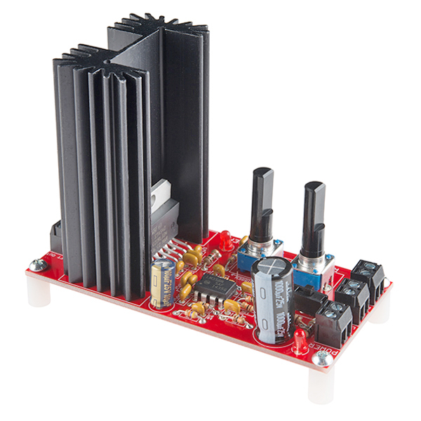
SparkFun Audio Amplifier Kit - STA540
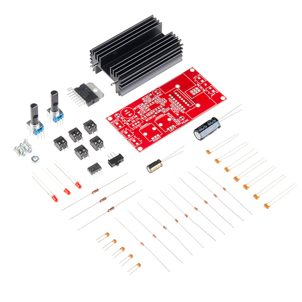
This is a stereo amplifier kit designed to make use of the STA540 power amplifier IC. Once this kit is completed you have a fully functional, two-channel audio amplifier, complete with a standby switch, volume control and indicator LEDs. The kit also includes a 6400BG heatsink for the STA540 to dissipate any damaging heat.
In this kit, the STA540 is configured as a dual bridge amplifier capable of delivering up to 2x 38W (4Ω at 18V). Power supplied to the kit directly powers the STA540 and should be within 8 to 22V.
This kit comes as a bag of parts, you'll need to solder everything to the PCB. All components are through-hole, so it shouldn't be too difficult; but this kit is a bit more complex than our other through-hole kits.
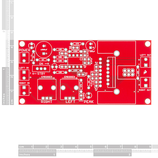
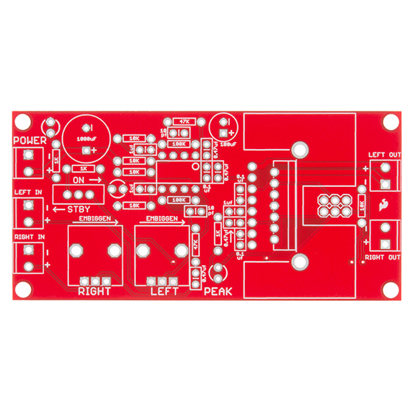
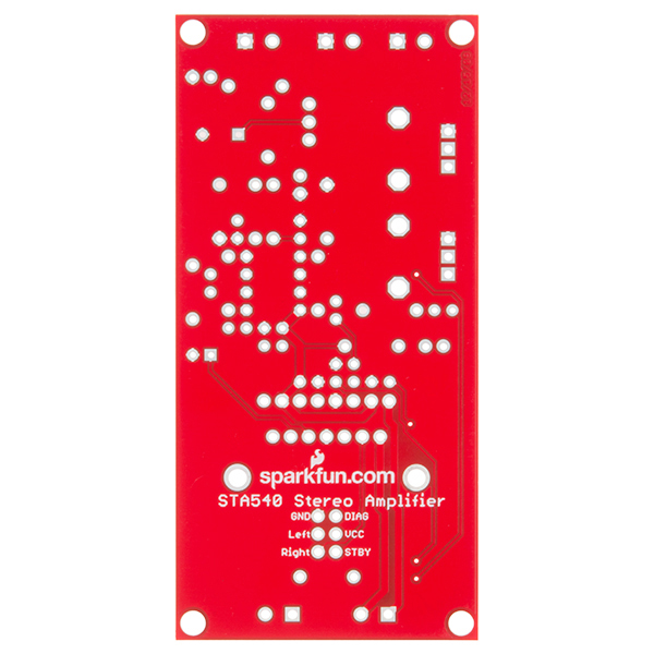
- 1x STA540 Audio Amplifier Kit PCB
- 1x STA540 Dual/Quad Power Amplifier
- 1x 6400BG Heatsink
- 1x LM358 Op Amp
- 3x LED - Basic Red
- 1x SPDT Mini Power Switch
- Resistors:
- 5x 10K Ohm
- 3x 1.0K Ohm
- 2x 47k Ohm
- 2x 100k Ohm
- 2x 10k Giant Trimpot
- Capacitors:
- 3x 0.1uF-50V-20%
- 1x 100uF - 25V
- 4x 0.47uF-25V
- 2x 10pF - 200V - 5%
- 3x 1uF - 50V - -20,+80%
- 1x 1000uF/25V
- 5x 2-Pin Screw Terminal - 3.5mm
- 4x Nylon Round Female Standoff
- 5x Phillips Screw with 4-40 Thread
- 1x #4-40 Hex Nut
SparkFun Audio Amplifier Kit - STA540 Product Help and Resources
Touch Potentiometer Hookup Guide
October 22, 2015
Learn how to use the SparkFun Touch Potentiometer to control lighting, volume or other inputs in your daily life.
My Kit Makes a Thumping Sound When I Turn It On!
Some users have noticed that their amp will oscillate or 'thump' when power is applied rather than operate normally. There are usually two causes for this and both are pretty easy to fix.
The first is that you may not have a power supply that can supply enough current for the kit to work. You need at least a 12 volt power supply that can provide 2.5 amps or more current. Supplies up to 20 volts will work but you still need 2.5 amps or more current to play it safe.
The second issue that can cause trouble is if you have a lot of flux leftover on the back of the board from soldering. We recommend that you solder all components except for the potentiometers first, then thoroughly clean off any leftover flux from the board. Once the flux is cleaned off, solder the potentiometers and you should be fine.
Buzzing Sounds and Decoupling Capacitors
Hearing a buzzing sound? There are a few reasons why you might be hearing a buzzing sound. We have heard of problems with the audio amplifier kit due to the power supply or needing some additional decoupling capacitors. If the power supply is not providing constant power and is noisy, there can be problems amplifying sound. Maybe the bench and laptop power supply units are not giving enough peak current to your STA540 Amp Kit. Also, try adding as a shunt capacitor to reduce the lower signals out of the amplifier as opposed to in series which would increase the lower frequencies. Try looking at this tutorial for more information on stabilizing the signal => https://learn.sparkfun.com/tutorials/capacitors/application-examples . This might help with any issues using the audio amplifier kit.
Core Skill: Soldering
This skill defines how difficult the soldering is on a particular product. It might be a couple simple solder joints, or require special reflow tools.
Skill Level: Rookie - The number of pins increases, and you will have to determine polarity of components and some of the components might be a bit trickier or close together. You might need solder wick or flux.
See all skill levels
Core Skill: DIY
Whether it's for assembling a kit, hacking an enclosure, or creating your own parts; the DIY skill is all about knowing how to use tools and the techniques associated with them.
Skill Level: Noob - Basic assembly is required. You may need to provide your own basic tools like a screwdriver, hammer or scissors. Power tools or custom parts are not required. Instructions will be included and easy to follow. Sewing may be required, but only with included patterns.
See all skill levels
Core Skill: Electrical Prototyping
If it requires power, you need to know how much, what all the pins do, and how to hook it up. You may need to reference datasheets, schematics, and know the ins and outs of electronics.
Skill Level: Competent - You will be required to reference a datasheet or schematic to know how to use a component. Your knowledge of a datasheet will only require basic features like power requirements, pinouts, or communications type. Also, you may need a power supply that?s greater than 12V or more than 1A worth of current.
See all skill levels
Comments
Looking for answers to technical questions?
We welcome your comments and suggestions below. However, if you are looking for solutions to technical questions please see our Technical Assistance page.
Customer Reviews
4.5 out of 5
Based on 17 ratings:
2 of 2 found this helpful:
This is fun and easy to build
I had this kit together in no time at all. I do have to say I am experienced in electronics, but I still believe that anyone can do this. One thing that could really improve this product is a 3 mm stereo input jack. This would make a nice clean connection for a iPod or for a computer. Now with that said, something really fun you can do with this is pair it up with a Raspberry Pi with Shairport (AirPlay) and you can play music right off your iPhone. VERY COOL. I hooked this up to my Pi and some in ceiling speakers. The idea is you could have a Pi per room in your house and listen to different music in each room. Here is the link on how to setup the Pi with Shairport: http://www.raywenderlich.com/44918/raspberry-pi-airplay-tutorial
1 of 1 found this helpful:
this amp is loud
had it together in no time, works perfect with my mp3 trigger, make sure to use a ground loop isolator, highly recommended. Cody from tech support was very helpful in my decision in choosing this amp, thanks Cody for all your tips.
2 of 2 found this helpful:
Absolutely Brilliant!
The simplicity, the clarity... omg the power in such a tiny little package. Add an option to bridge the input and outputs and you have a serious contender here. It's raw this is true but I've played with and owned pro grade qsc and crown amps and I'm simply blown away. And it only takes about 20 min to build if your serious about getting it done.
1 of 1 found this helpful:
Nice amp, nice kit, could use some polish.
I bought this kit in 2014 for a part of a project I didn't get around to. I've finally gotten around to finishing it and I'm impressed with its performance. I've noticed some background hiss (I haven't tried using a ground isolator as another review suggested) but the output is otherwise clear, even when turned up louder than I care to listen. (Hm. I should try temporarily replacing the amp for my my living room speakers with this and see what I think of it.)
Assembling the kit was straightforward, even though this was the first time I'd soldered any nontrivial PCB. (Make sure you have flush cutters — there are lots of bent leads you want to clear out of the way to get at the next joint.)
Here are some minor problems/inconveniences I encountered, some of which I think could be helped by changes to the design of the kit with little added cost:
• The spacing between the amplifier chip and heat sink is not quite right, or the assembly procedure needs improvement. I ended up with the chip being at an angle to the heat sink, not lying flat against it, which doesn't help heat transfer. (I'm glad I used a solid “thermal pad” which fills the gap with its thickness rather than heat sink compound.)
• It was very hard to read the capacitors confidently and tell them apart. I had to sort out all the capacitors and compare the number of each type I had to the labeling before I got them all straight.
• All of my audio sources have cables with plugs. While the screw terminals may be nice for using this as a component of a larger project, I think it would make more sense to include a 3.5 mm jack, or 2 RCA jacks, for input, and anyone wishing to direct wire inputs could simply leave the parts out and solder wires in place of the screw terminals.
• The included instructions say “connect 12V to the power terminals”. They don't mention, as the product description does, the larger 8V to 22V allowable range.
• I think it would also be worth mentioning that the input “-” terminals are wired to ground, and that the output “-” terminals aren't.
• The output screw terminals should be changed to ones that accept larger diameter wires or pins. There's plenty of room on that end of the board, and standard speaker wires can be pretty thick.
1 of 1 found this helpful:
Tech problem
I just assembled this kit, it doesn't work and has the following behaviors- can anyone think of an obvious mistake I may have made on assembly? - With 10VDC the power LED illuminates - With the switch on "Standby" the ON LED illuminates - With the switch on "ON" the ON LED turns off - With the switch on "ON," no amplified audio output, but a periodic thump every .25 sec and flash of the Peak LED as if a Capacitor is charging and discharging.
I'll assume user error here, based on the other reviews. Thinking I cooked a component or miswired. Any knowledgeable comments greatly appreciated.
Hello!
Have you contacted our technical support department @ support @ sparkfun . com ? They're usually very good at helping figure out issues like this!
Fun to build, works well
I built this to replace a BT/aux in amplifier in some powered speakers. In that, the BT would go off line with a power glitch. The aux in would drop out continually. I ripped that piece of junk out and installed this compact amplifier. It works as well as I hoped. Chromecast Audio is the input.
Functional, but more difficult to assemble than it needs to be
I purchased this to serve as a test-bench amp for some Thiele/Small parameter measurement work as I knew I could get schematics and parts for repairing the thing if it did spew magic smoke all over my bench (vs. a commercial stereo amp which might have unobtainium parts and no service manual to speak of). As a result, I can't really speak to its audio quality, although I'm sure it's reasonable for the parts list and price.
Assembly went fine until I hit step 12, where I ran into a 1000uF obstacle while trying to stuff the slide switch. I was able to retain it in the PCB by bending its pins with needlenose pliers, but the results were still undesirably cockeyed. Likewise, with step 14, I had to use the heatsink as a prop to retain the terminal blocks while I soldered them in. This could be fixed easily by moving steps 10/11 (the electrolytic caps) after steps 12-14 (the slide switch, LEDs, and terminal block). Step 13 itself is another potential pitfall as while the written instructions for LED insertion do a very good job, the silkscreen on the board has barely any visible indication of LED polarity. This could be trivially fixed with a diode symbol in the silkscreen layer, as documented in https://blog.screamingcircuits.com/files/led_markation_guidelines.pdf While you're at changing the silkscreen, by the way, moving the electrolytic cap polarity marks outside the footprint of the capacitors would be nice -- it'd sure make checking your work easier!
Also, like other reviewers, I had difficulty with getting the STA540 and its heatsink installed. I ended up (after some false starts) tack-soldering a pin on the STA540 to get the part to have the correct relationship with the HS while I soldered the latter in. Furthermore, the kit doesn't come with heat-sink grease, something that should be stated a bit more clearly at the beginning of the manual. Luckily, I had some Arctic Silver 5 left over from old PC builds, but this could really bite someone less experienced.
Once it was put together, I put it through some brief tests with the speaker DUT in question, in my case the 4ohm version of the Visaton SL87XA (a small, although high-power-rated, full-range speaker), and fed it a couple of 1Vrms sines (1 and 1.5kHz, to be precise) from my trusty function generator while powering it with ~9V from my bench supply. The amp functioned OK in this checkout, drawing ~400mA at low-ish volume levels, save for the regular popping or thumping other reviewers mentioned, which seems to be an internal issue when the amp is ON but lacks an input signal. I haven't done any probing around to try to reveal if the pops or thumps are coming from the input stage or the power amp itself, though -- it's not an issue for my intended usecase as long as it doesn't interfere with the measurements I'm going to be taking.
Overall verdict: functional, but no Heathkit -- the manual, while well-illustrated, falls short on a few rather irksome points, and the board silkscreen could stand to be improved in a couple spots as well. Also, while the popping isn't an issue for me, it's a much bigger nuisance in more...musical uses of this amplifier.
Unknown problem - got a full refund.
After assembly, I tried it with a lab supply I use for such things. At whisper volume the amp was fine. Increasing the volume resulted in a loud thumping and the Peak light started flashing. Tech support recommended a higher current supply. I tried connecting it to my car battery. Same problem. I was given a refund. I think the problem is that the amp is not rated for 4 ohm speakers as stated in the spec. or maybe there is some kind of feedback causing the pulsing.
This rocks!! (with the right power supply!)
THis little setup absolutely rocks. I bought this to make as a test rig whilst rebuilding my much more expensive amp. I needed something to test my speakers (which I was worried I had blown out when I shorted my amp). Yes there a few drawbacks but the sound is amazing. Initially I was using it to drive some old B&W P4 floor standing speakers, and it was amazing, but not quite great, but it turned out my speakers needed new ferro-fluid in the tweeters and once that was done it really does pack an amazing sound. I switched to a pair of Klipsch bookshelf speakers and immediately got the repetitive thumping that others have experienced. As other reviewers have noted, and from the instructions, you need the right power supply to get this to work. You 12V 1A supply you have lying around just wont cut it. I used an old 20 V 3.25A power supply from a laptop and boom all my problems were solved. It's so good I built a case for it, I replaced the on board pots with panel mounted pots, moved the on/off switch to the front panel and added conventional connectors for the input and outputs. It really is a great kit and with a few tweaks makes a great little amp for a workshop, garage etc...
So totally cool!
OMFG! With a phono pre-amp (ahem, sparkfun, you should sell a kit), this was epic! Listening to Steve Miller, Living in the USA, I was back in 1968! This is a really cool kit, easy to build, fun to implement. Thank you. With all that's digital and cool, don't stop making neat stuff like this!
Cool little guitar amplifier project
Easy project to assemble. I hooked mine up to two 30W Celestions and an Ubuntu Studio box doing stereo guitar effects processing. That, plus a little op-amp preamp to provide a high-impedance buffer between sound card and the guitar (important!) makes a full-featured guitar amplifier project. A little extra work to make a cabinet for it and it goes places too!
Great amp project
Bought this to drive a pair of 40W bookshelf speakers - now I have a great computer sound system!
Easy, good sound, and well worth the price.
I was BOM'ing an amp for a project using a different chip. Once I hit a certain dollar amount, I thought 'hey, I wonder if there's a kit.' Found this jewel, and glad I did! So, here's "just the facts:"
- well made plated-through PCB with solder mask and component silkscreen
- circuit implements a manufacturer's reference design for the IC in 2-channel BTL mode
- component selection is reasonably conservative, nothing is working too close to its allowable rating
Just my thoughts:
- this is a quad amp IC bridged into stereo BTL- the people who built the kit and just got thumping out are probably trying to ground the outputs!
- to reiterate that- the output + and - are for speaker phasing, do not connect them to ground! Both sides are driven, like an H-bridge
- do bother to look at the IC datasheet, it will answer most questions and fix most problems
- its form factor is a little awkward for trying to come up with an enclosure
- never mind the "38 watts"- again, look at the datasheet, consider speaker impedance and power supply voltage
- I am going to buy it again for another project!
Random: I would knock 1/2 star for mechanical considerations. Nothing that couldn't be worked around. What works best for me may not work best for you, and this is not a finished consumer product, it's a kit!
Good Kit with Minor Flaws
Overall the amp is a nice kit with great sound and small but simple construction. This kit did not come without a few flaws that I noticed as I constructed and used this amp.
First, the standby switch is in a terrible spot for even moderate use. If you plan on putting it in a small case like I did, then you won't even be able to get to it. The pots are long enough to protrude from any case but the switch is buried deep in the board. That's a moot point though since my switch didn't even last one day before it failed and wouldn't switch Vcc to the STA540 to disable standby mode. It only switched Vcc to the Standby LED which made this a little harder to diagnose. I have since removed the faulty switch and placed a jumper there. This is not my recommended solution though as now the only way to tun it off is to remove power. This typically results in a pop from the speakers.
Second, the individual pots for the left and right channel volume. This is definitely not a deal breaker as it isn't very difficult to get them close enough to the same volume for most listeners but might be an annoyance to some. Dual pots specifically for stereo channel volume control are readily available and I would have paid an extra dollar or two for a kit that was designed around one just for the convenience.
Finally, the size of the screw terminals is a bit too small. The largest size wire they seem to accept is 18 AWG and its a tight fit. Be careful when putting 18 AWG speaker wire in that you dont have any strands poking out that cause a short circuit. Terminals that fit 16 AWG and even 14 AWG might have been a better choice here.
I would still recommend this amp to anyone looking for a small amp kit with plenty of power for bookshelf speakers. I will be using this as a stepping stone to design my own amp with similar components to fit my needs. Nice work Sparkfun!
Great amp
Seriously great amp, especially for the price. Good quality sound, and powerful.
Questions: When hooking up the audio from an MP3 Trigger to this, what do I attache the Audio Ground from the MP3 Trigger to on the Amp? Would it work to share the power source from an MP3 Trigger board? If so what kind of power supply/voltage should I use?
1) You attach it to the negative side of the input of whichever channel you're looking at. But I would caution you to read up a bit on the MP3 Trigger and understand the use of GBUF (you wouldn't use it here) and some of the jumpers on that board before attaching it.
2) The amp board really needs a good 12V or better to give good performance, and that's the max rated for the MP3 Trigger. But the regulator on the MP3 Trigger is linear, meaning that it's going to drop all of it's extra power as heat, and kind of a lot IMO. If it were me, I'd probably start with a larger supply, like 12-15V, and regulate down to something more reasonable for the MP3 board, like maybe 5-7V.
Could this be modified to accept balanced differential inputs by bypassing the pots and feeding the differential signal directly to the + and - of the LM358 opamps?
Just finished watching the According to Pete videos for his stereo system (awesome) and I have this kit in my cart awaiting purchase. My one (newbie) question is why do you need an op-amp for the L and R channels before it hits the STA540 (especially with a gain of only 2x from the op-amp)? The STA540 has a 10x amplifier; why not just feed the source audio signals into the STA540? Will the source device not provide sufficient current to drive the STA540 or are you just using the op-amp for filtering?
Love the "Embiggen" labels on the PCB. :-)
Could you actually bridge the two outputs of this kit again? I want to use one of these per channel.
PLEASE NOTE: This kit does not come with heat sink compound, though it is mentioned in the directions. While it is not necessary, the compound will help dissapate much more heat. Check out PRT-09599 to order, or look in the related products below.
ALSO: Step 15 shows a picture of a resistor, not one of the potentiometers. Please don't get confused by this. Thanks to one of our observant customers for pointing that out!
Be careful about hooking circuits straight up to the "12V" vehicle rail. They are only nominally 12V, and can give damaging voltages (up to 100V or more) during cranking, etc. Some chips are designed to tolerate high voltages, others aren't, so just make sure it'll be okay.
If not, another regulator is needed before the circuit to insure they only see voltages in a safe operating region.
mct75: This kit seems perfect for a car audio application, assuming the output is high enough.
i think you're a bit confused here. the 12V DC in vehicles is drawn from the battery. and only the battery and not through any kind of wire windings (transformers, coils, etc.). most vehicles have a 12V battery (14.x V MAX) which the battery will never, ever, be able to just suddenly drop over 100v into the system, even during 'cranking'. sure, the starter motor might draw lots of current, but its still at a nominal 12V and is completely isolated on its own circuit controlled by a solenoid activated by the ignition switch. if every time the car was cranked, 100V of DC went through the system, every incandescent light that was on would burn out in short order and im sure that the computer systems would be....compromised. now, if you wire this thing to the output of the ignition coil in place of the spark plugs things might be different, then again, your stereo would now be in the engine compartment ;)
Actually, it's true that the 12V rail can spike at times. Ever wonder why the stereo, interior lights, and all the other accessory circuits shut off during cranking?
A spike on the 12V rail is more like 13.8V, not 100V. During cranking the voltage drops to about 9V.
I just assumed they needed all the current they could get. The alternator wouldn't be running at start-up would it?
In actuality, there are a number of voltage spikes in the automotive 12 VDC system. The ripple from the alternator, especially at high load, HV spikes from start solenoid disengagement, other coils and actuators, etc. An isolated input would be wise.
And to the Gent RE: battery noise.." what's cleaner than a 9V battery", depends on the chemistry. the newer chemistry's have much lower internal resistance, producing cleaner(quieter) power. Earlier types required a bit of filtering to produce a clean current. Try a 9V lithium type. FWIW
The 100v spike he's talking about is called load dump. That's what happens if the car is running and someone disconnects the battery. The sudden loss of load on the alternator will cause a voltage spike until the voltage regulator in the alternator is able to compensate. They're rather slow regulators, and the spike can happen pretty fast. Also, I've seen a continuous voltage, in a car, of up to 18v. That was as the result of an internal short in the alternator which cause the regulator to work wrong, and it severely over-charged the battery.
Put some capacitors on the rail to limit ripple.
Can anyone explain why there are op-amp circuits on the L and R channels before it hits the STA540? The STA540 is the amplifier; why not just feed the audio signals into that more directly?
If i put this amp in my car am I gonna have problems with the power supply ? My car battery is 14 V. I tried one of these other kit build amps (from jaycar) and found that when i connect it up to car battery sparks flie off the terminal and the amp chips burnt out. In fact the capacitor burst open. I think PaulC is right when he says dont hook these straight up to your 12 V vehicle rail. They must need some sort of protection. Does a normal car stereo have some kind of current limiting protection between the battery and the amp/stereo. I really want this amp but i dont want to pay for it and have it burn out like my last two.
I built this kit and connected it to an 18.5V laptop power supply. It sounds great and has plenty of power. I am driving a pair of salvaged Kenwood 30 Watt 6 Ohms speakers with it. Using an oscilloscope, I measured about 17Vpp and figure I am getting about 25 Watts continuous power from the amp. The heatsink gets pretty hot so I may need to put a fan on the enclosure. I like the mounting holes (wish they were standard on all boards from Sparkfun).
The only oddity is the potentiometers. They are too short to reach a front panel because of the large heatsink. On top of that, they are linear taper potentiometers and that isn't great for a volume control you use a lot. I replaced the two potentiometers with a 100K ganged pair of audio taper potentiometers and mounted that on the front panel of the enclosure. I lost the ability to control balance, but I can always add a preamp/tone control with a balance knob if that ever bothers me.
if you wnted to use the ots that came with it you coud have mounted the pots on the underside
Hmm, problem. All of the tests with the multimeter check out, and I have a nice, regulated 12V 8.5A power supply. But, when power is applied, the peak LED lights up. When I switch the amp from standby to on, the peak LED is still on. Never goes off. And I'm not getting any audio output either. Anybody know what's going on?
Btw, Member #491199 had the same problem but no one ever gave him a fix for it
The amplifier chip says it can operate in quad, but this kit is just stereo, correct?
I get no audio output though. And the peak led is steady on as soon as the switch is turned on.
By the way I put 12v to it
I have this all assembled and plugged in power led is on and when I standby, the on led turns on and when I switch on the on led turns off and the peak led turns on. I am skilled at soldering it is assembled properly and testing is correct ohms. All seems to check out until power is applied. Did I get a bad sta540 or lm386 op amp?
I contacted tech support about this same issue and got the following response "Looks like we have a typo in the documentation for this kit. The LED should be on when the switch is in the standby position (audio off) and off when standby is not enabled. (switch on, audio on)".
Also the schematic doesn't match the PCB.
Do you have audio output? And is your peak led on?
I have audio output but as soon as the output goes above a certain level I get the same motor boat/pulse with peak LED on that a number of others have reported.
I think the pulse issue has to do with the quality of the power going into the amp. I had the same issue until I switch the power supply. The one that caused the amp to pulsate was rated for 12v but when measured unloaded gave 15v. The one that worked was also rated for 12v but when measured unloaded gave 12v.
Can you publish a PDF with the mechanical dimensions of the kit, including the mounting holes? Thanks.
Just finished this build and DMM test were fine but everytime the switch goes to ON position the PEAK led flashes and the middle one goes dim and nothing happens. Any thoughts? Supply is 12V 0.7Amax
I was seeing this when I was limiting the current in my power supply. But I think at 700 mA it worked fine.
Hello Sparkfun forum,
I am a newbie so forgive me if I ask basic questions.
The plan is to use the SparkFun MP3 Player Shield https://www.sparkfun.com/categories/273 to play an mp3 file. The MP3 file would be downloaded onto a MicroSD card from a PC. The SparkFun MP3 Player Shield would be activated by a PIR sensor http://www.parallax.com/product/555-28027?SortField=ProductName,ProductName The SparkFun MP3 Player Shield would out put to a stereo amplifier SparkFun Audio Amplifier Kit - STA540. The SparkFun Audio Amplifier Kit would output to a pair of 8 Ohm speakers
Is this the correct configuration? Does the SparkFun MP3 Player Shield require programming?
Thanks
Allen in Dallas
I built this last night. The kit had all the parts and directions were clear. I am taking input from my PC using a 3.5mm plug and going out to real hi-fi speakers using a 19v 90w laptop brick for power. It sounds great and plenty loud to fill a room. A fun way to embiggen the sound from a PC or ipod. A magnifying glass was helpful to read the numbers on the small caps.
Set up my board to take its signal from the aux channel on my churches 24 channel live sound mixer board to power a set of extension speakers in the lobby for overflow during the service. It is driving two 8 inch 40 watt full range speakers and it is working very well. I had thought we were going to have to let go $200 or so on an amp but this thing works great.
How large a speaker can you drive with this? Would it be useable as a guitar amp?
Hi Guys
Could I replace the potentiometers on this board with digital audio controller such as the PGA2311 from Texas Instruments? http://www.farnell.com/datasheets/1831444.pdf
Has anyone had trouble using the SparkFun 12v wall adapter to power this? The adapter should be able to source 600ma, and according to my ammeter, it's only drawing 110ma. Still, the audio quality goes to crap whenever I hook it up to this power supply. I have two of the wall adapters, so I think it's unlikely the the problem is there. I'm wondering if maybe the amplifier has spiky draw, and the little wall transformer can respond quickly enough.
I would guess that that's exactly the problem. Amplifiers require quite a bit of instantaneous power for the audio peaks; your averaging meter may not be showing that draw. Hopefully a beefier supply will solve your problem. If it doesn't, let our Tech Support department know.
Mine is completely assembled, I am using a 1A ~18V power supply and when I plug it in, the speaker just starts repeatedly thumping and the peak light flashes. Using it for a school project to run a sub eventually, what do I need to do to fix it?
Would this work with one 4" Extended Range (25W, 8 ohm) speaker per channel
Yup, I think that should work just fine.
Hey guy I put 19v to it and the lm358 burnt up. What did I do Wrong? Ive double checked it and I cant seem to see anything. Thanks
Could I use this to make an FM transmitter, with an audio jack and the FM Radio Module Breakout Board - NS73M?
What voltage is optimum for the amp? canpop
I seem to be having some problems with this, firstly when on standby I experience a buzzing noise throigh the speakers, then when playing music a slight echoing can be heard and finnally when I put the volume up to a certain level the peak led flashes and speakers move in and out slowly, but a long way. I'm using a pair of speakers from an old bose docking station and have no information about them. Any suggestions?
I just finished building this kit and it worked perfect the first day, then the following day I turned it on it just had a loud buzz when the power is switched on. No sound will play from an input source, just a loud buzz. The volume knobs are ineffective to control this buzz. Any thoughts?
I'm fairly new to soldering and finished this kit in about 3 hours. i do have one question though, maybe someone can help.
i'm using a 12 V power supply with 1250mA it sounds amazing when i attache one speaker to the amp but, when i plug two of them i get a popping sound from the spakers. anybody know why this is happening?
If you haven't figured this out yet, or if you have this might be useful for someone else, the pop is because you aren't supplying enough current for the amp. You will want to use a higher voltage or higher current power supply to get the overhead needed.
As an exercise, you can hook up the power to a car battery and notice that there is no popping. This is because the car battery is basically able to push out as much current as is requested of it.
does anyone know if this amp runs cool enough to use in a sealed enclosure? or would it need to be coupled to an external heat sink? I'm trying to use it in an outdoor bluetooth project.
A breeze to solder if your experienced, but would def suggest getting some heat sink compound, as the unit gets quite warm even with said compound. Also consider some big ole caps or a regulated power supply, as problems did arise when I hooked it up to my '81 BMW with questionable circuitry. Engine noise was passed through and amplified, but luckily did not damage the unit. Also pwm noise from the TLC's that run my interior lights was amplified. This is no high end head unit, and the base isn't great. But for the price I'm very pleased. Loud enough to drive a pair of car speakers at a good volume and clarity, even on the highway with the windows down. Would love to see a dual pot included, but they are easily acquired elsewhere.
I want to wire four speakers to this amp. What type of speakers should I use? 4 ohm or 8 ohm? and at should the wattage should each speaker be rated? I am a novice.
Anyone ever use one of these with an Arduino and a Ladyada Wave Shield? What was your experience like? I used Ladyada's small amp for an art project that is near a street and found that at full volume, it still gets drowned out by vehicle noise. This time, the same piece is going to be installed at a fair and I think noise will be a problem again so I'm trying to make it louder. I'm using a Jensen JXHD30HPC which is 4 ohms and 60W max.
Any thoughts? Tim
Inconsistencies in materials. Parts list in the item description and the first page of the instructions show One 0.1pf capacitor. In the actual instructions, and on the board, it shows Three 0.1pf capacitors. My kit included Two 0.1pf capacitors. Fortunately, I had some in my bins. Also, kit calls for heatsink compound, which is not included. Either include it, or make note in the description that it will be needed.
And a suggestion, make the potentiometers horizontal mount instead of vertical, so they can be extend from an enclosure. And put them farther apart. There's no possible way to put knobs on them as is. I'm probably going to put them on a separate board, wired to the main board.
I just received this kit in the mail. Instead of 3x 1.0k Ohm resistors - I got three 240 Ohm resistors. I suppose I could go to radio shack - but kind of sucks!
The inputs each have a positive and negative. I have salvaged a male to female mini stereo jack extension I use with my iPhone that has three wires. It looks like the ground is shared. Can I run that shared wire to both the left and right input of the amp? Any pros, cons or better suggestions?
The final use for this project is a set of external laptop speakers driven from the headphone jack on my MacBook Pro.
Cheers
Troy
Hey Troy. I'm using the same setup as you and yes, you can just connect the ground wire to one or both of the negative terminals. The negatives are connected on the board. Works great for me! Good luck with your project! Chris
Uh... anyone know why is there a jp12 & jp13 in the schematic, but I only see 5 2pin terminals in the BOM, and the extra terminals don't appear on the images of the board either
When in doubt, try opening the Eagle files - and use 'show jp12', or even 'show @ jp12' to find where the component is. In this case, JP12 and JP13 are the two rows of 3 pads (chosen perhaps because the designer couldn't spot a 2x3 component) by the cooler, and further identified on the bottom of the board. What you'd use them for, however, is another matter. Looks like it's access to the power (VCC and GND), the diagnostic pin on the STA540 chip, the left/right input signals pre-amplification but post op-amp and some filtering, and an alternative means to toggle standby mode (e.g. from a microcontroller, rather than flipping the switch).
If I substitute a100k pot for the volume control, should I change the value of R2 & R4
HELP!!! I am a complete novice with electronics. I've only recently started teaching myself how to solder electronics, so I don't have a bag of troubleshooting tricks...I have now built the amplifier twice (brand new from scratch) and am having the exact same problem both times. I've connected the amplifier to a pair of .5W 80hm speakers (from sparkfun). Each speaker produces a thumping noise, one louder than the other. I am using two 9V batteries for power and connecting my iPod through a 3.5mm audio jack. I am absolutely sure that I soldered all parts correctly, especially the second time around. I have swapped out a different speaker, to rule out speaker issues, and have soldered two different audio jacks. I cannot figure out the problem.
Can someone please tell me what I am doing wrong?? Thanks!
Check your S1 switch. My kit had a small 4 lead pushbutton instead of the slide switch. I sent an email to tech support.
Got this kit built and have tried it with a 16 volt laptop power supply and a 12 volt ATX computer PSU and the sound seems slightly.... off. I'm using some decent Boston Acoustics speakers and the sound is a bit hollow, for lack of a better word. As though there was perhaps a little echo in the high frequencies. Is this normal for this amp? If not, any ideas on what the cause good be? Bad solder joints or PSU noise, perhaps?
Never mind, it was the speakers. An unused pair of dipole surrounds. I guess the dipole design created a set of reflections that sound odd when used as main speakers. Hooked up a pair of ancient Altec Lansing Model 3s and the rig sounded fine.
I've built a couple of these kits and they are great.
I've interfaced one with a Kemo M040N universal pre-amplifier. Again, the sound quality is great, nice and loud.
http://www.parts-express.com/pe/showdetl.cfm?partnumber=320-555
BUT
If I turn the volume up more than about 20%, the amp looses control, and just starts rumbling.
If you look at the wiring instructions for the Kemo Preamp here:
http://www.kemo-electronic.de/images/ipics/M040N/M040N_12020DU_ans.png
It shows the input and output, and DC negative, all tied together. That's how I have it wired up. However, even with no audio signal, the amp just starts rumbling like crazy.
If I power the Kemo from a separate DC supply, then it works perfectly, up to full volume. Clearly the signal is coming from the power somehow. My intended application is running from a 12V battery, so separate power sources will not be an option.
How do I isolate the DC inputs to each part? I guess I need way better filtering for the power amp.
I did some more testing, and I am measuring up to 1V AC on the DC input pins while the amp is "motorboating". If I turn down the gain, then the voltage goes away as the noise stops.
I tried adding a couple of capacitors (100uF) to the DC input, that didn't do anything.
There has to be something I'm missing...
In instruction manual step 9 only 2/3 of the 1uf capacitors holes are highlighted in green, it sais on pcb but not in manual
I'd kinda like to see this board offered with a dual gang volume pot and a balance control. The single pot per channel configuration can sometimes be inconsistent unless low tolerance components or measured matched pairs are used. That said, I'll take 5 please! Should make a nice stand-in until we get around to our LM3886 based hijinks.
Really wish you guys carried some stouter PSUs too. You're just so awesome, I wish I could order all of my components here.
Is there any way to buy just the PCB? It's been awhile since I soldered and I didn't realize how bad my sight has gotten in my old age :), and I ended up lifting a pad and burnt the trace between c7 and r6. I accidentally soldered in a .1uf cap instead of the 1uf and was trying to desolder it when the accident happened. I was using a low wattage iron and I just couldn't get that sucker out of there - I think I applied the iron to long and the pad was toast. The trace also got fried somehow. I can easily replace the components I did solder in (I have probably 5 of each in my parts box) and can easily get another lm358. I just hate to throw away $40 (after shipping) because of my old man eyes.
I searched the site and couldn't find just the PCB for sale and lack of a response leads me to believe that you guys do not offer just the bare PCB. Rather than dish out another $40 (which I refuse to do) can I frankenstien this guy? I want to be able to breadboard the two channel preamp with the lm358. I can then solder the st540 onto the original board and jumper the inputs to pins 5/4 and 11/12. I think I can even cut the traces from the original lm358 and just use the line out as line in (and give up my line outs) that is jumpered from the breadboard with the lm358.
Is this even possible or would you advise against it? I really want my amplier - it's going in a MAME cabinet with my raspberry Pi - but I can't justify throwing away $40 because I soldered in the wrong cap (and subsequently screwed things up because I can no longer see small things).
Thanks again for any help in advance!
Sorry about not replying earlier. As you've seen, in general, we don't sell bare PCBs for our kits. But since we do provide the design files (the "Eagle files" above) for our products, another option is to use the design files to order a PCB from our BatchPCB service (or the boardhouse of your choice). For this board, I believe BatchPCB would cost $10 handling, plus $2.50 per square inch, so you're probably looking at $25 plus shipping. PCBs are a large portion of the cost of a kit.
But as you say, you can (and we've all been there) do whatever Frankenstein engineering you need to get a damaged board working. Often you can keep parts in the same location, and solder in above and below-board wires to bridge the damaged traces. Whatever you do, good luck and we hope you get your amplifier working!
Mike, you guys are the best! I got your email and thank you so much! I've said this before and I'll keep on saying it: Sparkfun is the greatest!
Haven't had to do any serious soldering in almost 10 years and wanted to back into electronics/audio. Took about a hour to build. Hooked it up to a 13.2v DC 3.5A power supply for an old bag phone I had about 10 years ago. Fed it signal from the record out on my receiver. Attached a couple of 10 year old Optimus Pro-X55AV (5" woofer/ 1" tweeter) 8 ohms. And fired up Pandora, everything works and sound great! Now for a pre-amp....
This with digital pots + TDA7719 and you got quite the audio playground.
I have a 19V 6.3A laptop power supply. Would that be any good? im going to connect the amp to an old recordplayer and two old 60w 8ohm speakers? I dont have much experience with this.
Can someone clear something up, please? The instructions in the assembly instructions dictate a 12V power supply. However, the product page on SparkFun claims "Power supplied to the kit directly powers the STA540 and should be within 8 to 22V."
Which is it? 12V only or between 8V and 22V?
Enter a replyMy question too. What voltage is optimum for the amp?. Canpop
I was having the same problem as everyone else: the ~5Hz thumping sound.
I thought there was no way it could be due to a noisy power supply since I'm running it straight off of a car battery (charged by solar panels). I was wrong.
The onboard 1000µF bypass capacitor on the power input is really totally insufficient for this amplifier to remain stable. I added another 10000µF (probably overkill) just before the power-in to the board (with a Schottky diode on the battery side) and now everything is running great. Also added a pair of 0.1µF mylar caps on the input lines to remove some of the excessive bass (since I live in an apartment). Some sort of eq. would have been nice instead of an extra volume knob...
Other than the couple of small design issues, this amp is great and was really fun to build. It's insanely loud, even driving 8ohm speakers from only a ~12-13V supply, I have to keep the volume knobs at about 1/4 in order not to feel like a bad neighbour (although I sometimes see the 'peak' light flicker for very brief moments, even at this level -- but only so much that can be done with using a 12V supply to drive 8ohm speakers).
Finally time to decommission my dad's old 1970s Kenwood... a sad day. :(
I replaced four 0.47u ceramic ? caps with audio-grade electrolytic 0.47 caps and I think sound quality has been improved. It will be nice if in future the PCB design is modified to make slightly larger area around those caps.
Can this be used with the am fm shield
Would 2x LM386 (one for each channel) do the same job? Thanks :)
Yes except the possible max output power around 1W per ch.
Hey, I am trying to turn my old car speakers into studio monitors for a friend. i want to put one 6" and one 6" by 8" in each cabinet. they are 4 ohms each. would one of these per cabinet work for me?... any info is apreeciated...Thanks!
hey looking to turn my old car speakers into studio monitors for a friend. I want to put one 6" and one 6" by 8" in each cabinet. both are 4 ohms... would two of these work for me?... any info is appreciated Thanks!
I was trying to use this to amplify the somo4d audio player but it hasn't worked. I'm not sure if it can work. Does anyone have any advice?
These two should be able to work together. First, ensure that everything's working separately: try running a different audio source (ipod, etc.) into the audio amp. Also try running the SOMO's speaker outputs directly to a small speaker. Are both sides working separately?
If both sides are working, try connecting the SOMO's audio out (pin 14) and ground (pin 9) to the input of the amplifier. (If you only have one speaker connected to the amplifier, be sure you're running the SOMO into the same input channel). It should work!
Edit: if the amplifier doesn't work for any audio source, contact our customer service department - we accidentally sent out some kits with the wrong resistors and you may have gotten a bad one.
I have been trying to use this amplifier with the somo ad4 audio player, with no luck. I was wondering if anyone has gotten this to work or if anyone knows if it can even work.
Warning: Make sure you triple check the resistors that come with this kit. I reveiced 2 kits with 1meg instead of of 10k resistors/
I received a similar wrong kit. Rather than 10k Ohm (brown-black-orange) I received five 10M Ohm (brown-black-blue) resistors. I foolishly soldered everything together and found the problem during final testing with a multimeter. Sigh. I know, I know, RTFM.
I'm sending an email to SparkFun to have them check this batch of kits.
"So, solder pump, we meet again."
We had a mix up with the resistors. Please contact customerservice@sparkfun.com and we'll send out the right ones to you. Please make sure to reference your order number! Sorry about the inconvenience with this!
-Casey, Customer Service
I have a question. Can I use a simple ON/OFF switch and eliminate the standby function?
sure. I'm not 100% sure, but you might get a popping or something from the speaker if you just switch on and off power. Test it out and see. If that happens, you might want to use the standby instead, or some combination of the two.
Shouldn't get popping turning on the amp as long as you 1. Turn the input on before the amp 2. Turn the amp off before the input 3. Turn the amp off before unplugging the input
Embiggen: it's a perfectly cromulent word.
Can this amp be bridged to mono mode, per chance?
Hello,
I bought 7 kits to make a multi room, multi zone audio system. I installed them in a big box, in the basement, next to each other.
I am having 2 problems:
crosstalk between rooms. If one module is cranked up, and another is not used, i.e. input not connected but normal gain (half way), there is some crosstalk. I use a PC power supply to power them. I think the crosstalk goes through the +12V power wires. How come? What's happening? How can I fix it?
idle buzz. When the system is not in use, the input is disconnected, but the gain is at its normal setting (half way,) there is a faint buzz on the speakers. How can I alleviate that issue, since I cannot remotely control the gain potentiometers. What about the STBY vs MUTE? What's the pro/cons?
Thanks in advance. -k
Crosstalk can be from a number of sources, but I suspect yours is from grounding. Whenever you use multiple amplifiers from a single power supply, each amplifier's large ground return current causes a small audio voltage to appear on every other amplifier's input ground. This appears as input signal and gets multiplied by the amplifier gain (26dB) and so, crosstalk. I have spice simulated both the cause of and a solution to this problem. Typically if you use multiple amps operating from a single supply, the crosstalk is about -40 to -50dB, which you can hear in the quiet rooms.
The brute force solution is to use differential inputs or transformers on each amplifier input. The solution I used is to isolate the input signal ground of each amplifier (input connector, input network, feedback return) from the output grounds (speaker and power supply returns) and connect them only at a single point, back at the audio sources. This only works if the sources (preamps) are fairly close to the amps.
My DIY house-wide audio system uses two LM3886 amplifiers for each room and uses this technique with good success. To see details, go to http://www.djerickson.com/stm32/preamp1.html and search for "ground trick".
I don't yet know how to do this for the STA540. It uses a clever internal configuration that may make this technique hard to implement. However the SparkFun board does have a separate input op-amp that may be re-configurable as a differential amplifier.
As far as the noise, the STA540 has about -50db of power supply rejection at 300Hz and higher frequencies so you may hear power supply noise on the output. Try one or two large (10,000uF 25V or 35V) caps across the power supply to see if that helps. Watch the polarity!
Dave
Hello Dave,
Thank you for your note. It seems that our projects have some similarities.
Here is how I solved my 2 problems:
crosstalk was carried on the +12V wires, not the ground. I experimented with LC filters and found a good one. The idea is that the large cap (15mF) near each amplifier board provides for the current spikes. It is fed at a constant rate from the power supply through a L, containing the current spikes within each board
idle noise is suppressed using the "mute" signal. I control the amps with Linux boards and I use a GPIO from the CPU to control the amps mute
I started reading your website. Looks great, and I am looking forward to reading more; I'd like to stay in touch with you for future projects. This one was a quick demo, but if it catches up I will need to improve and make it a real product.
fyi, I've been using a switching PSU, salvaged from a PC, and it was OK for the amps (+12V) but not OK for the Linux boards (+5V). Too much noise. I used a separate switching PSU for the 5V, it is very clean, but now I have to be smart about tying the grounds together for the "mute" feature. Any idea or best practice?
Cheers, -karim
perfect amplifier and yes ill say it again its as good quality product as any on spark fun. love the pcb Sparkfun have made bright, those green ones are so dull.
Is there a public wishlist for this kit?? I want to integrate it into the breadboarded 1/8" stereo TRS to speaker wire adapter I built...
Hi, has anyone tested whether bridging the STA540 into a single channel configuration would work? Eg. do not populate C12^, and bridge left and right channel from JP13, and connect speaker to both left and right ch (connect OUT1 and OUT3 to one side and OUT2 and OUT4 to other). Or will it just blow itself up from some internal channel mismatch? (Pete-O? :P)
^ the right ch pot and lots of other right ch components are thus unnecessary, but I list minimum changes, not minimum components...
EDIT: Given some more time to figure out some more numbers, I believe the 2x24W at 14.4V (to 4 ohm) is continous sine wave power, which is consistent with the voltage limit, thus you cant get more power from that voltage by bridging the outputs (you could drive a load with less ohms, but that is unnecessary for me). Note that the peak power to a speaker is already 48W in that mode. I have a 120W car laptop PSU (20V 6A) that I think I could purpose for driving this thing, giving atleast that 2x38W continous, or 76W peak to a speaker. (Actually 2x76W > 120W, so better place some big capacitors on that thing...)
So yeah, I think I'm gonna boy one of these for driving my car rear speakers someday, with boosted voltage it should be totally enough power for them, and for a great Watt/EUR-ratio :P
I'm a big fan of this kit. Great buy.
Just finished building the amp about an hour ago. Sounds great. I bought some in wall speakers from monoprice and they sound awesome. Very loud. I'm using an acer laptop power supply.
Are the 10k Pots used for the volume a standard linear taper or are they known as "audio tapered"?
Standard linear POTs will work fine.
I'm wondering If I can control the volume with a AD5206 Digital Potentiometer and an arduino ??
Seems like it might work ?
Hi there!
I'm wondering if it would be possible to connect two different stereo line-out into this amp and get one stereo speaker-out from it?
The line-outs come from two MP3 Trigger v2's, which are having a GBUF instead of GND. It would be nice if someone could verify this? :)
I'm not sure about the GBUF since it says I can damage equipment with a ground loop.
I've made a little schematics here -> http://dl.dropbox.com/u/16857922/audio-circuit.png
Thanks for any help!
You'll most likely throw off the gain from the preamp. Not saying it couldn't work, It just might not sound as well as you want it to. I didn't actually work out any equations so I don't know where the operating range changes to. You're on the right track. You might just want to add a separate pre-stage for mixing down two sources. Just connnect the output of this to the input of the amplifier kit.
Something like this. -> http://static.electro-tech-online.com/imgcache/6282-opamp-adder.gif
Not sure how much you know about op amps but this may help. -> http://www.facstaff.bucknell.edu/mastascu/elessonshtml/OpAmps/OpAmp3.html
I tried designing a mixer in college for a lab project. I soldered everything and ended up frying several op amps because I didn't look for extra traces. Lesson learned.
It would be great if you guys would put together the 4 channel version and put the traces in for the mute
If you look at the STA540 poweramp datasheet they show a way to implement a mute function. On page 20 section 6.10. You could add it if you wanted too. But maybe in the next revision it will get added.
Hi! Correct me if i am wrong, so volume is controlled to each channel by potentiometer? if it's true then how can i control both channels in same time (without turning both knobs in same time)
You would need to control both at the same time, as you say. You could get a stacked potentiometer and control both at once, or you could use a digipot to control them through a microcontroller.
sorry for the comment to an old thread, but I am looking for clarification. Could I tie both pots together and just use one 10k pot. Looking to control volume for both channels with minimal effort (single 10k pot). Thanks!
you certainly CAN, but it's not really the best way to go about it. they make stereo pots (unfortuantely we don't sell them), but they are pretty cheap and that's how they're used. one knob, two outputs.
would the outcome essentially be a mono across 2 outputs with the single tied pot?
yeah, if you used a single pot, it would essentially sum the inputs and get a stereo mono signal. check the schematic, the pots basically attenuate the inputs, so if you use a single pot, it's going to tie left and right together. a stereo audio taper 10k pot is your best bet.
BUT, that being said, why not just control the audio volume at the source? if you're using an mp3 player, computer, etc, you would just turn the knobs on the amp up to full and adjust the volume on your source.
thank you for advice! so basicly I'm planning to plug a laptop battery charger as a power supply (19,4VDC, 4A, 90W) and to control both channel volume in same time (as you adviced) double potentiometer 2x0.4W, linear, 2x100KOHM. Will it be ok?
Close, but 100k might be a bit much. The ones on there are 10k. Find a 10k instead and you should be fine.
Could we please get some eagle files for this?
will i be able to connect my tv to speakers through this kit and get a decent output from the speakers?
I just finished putting this kit together and the sound quality is great!
I do have a question about the LED thats supposed to indicate the status of the ON/STBY switch though.
The final page of the instructions say that the LED should turn on when the switch is flipped to ON.
Mine is the other way around. The LED is on when switched to standby, and turns off when I switch to ON.
Did I do something wrong or is this a misprint in the instructions?
Would this work with the 3.3v somo14d audio module?
would this be safe or recommendable to use with a somo 14d sound module to control the volume of the audio in key mode.
anyone else have a popping problem? The amp just starts popping for no reason..
Yes, I have this problem too. I tried different power supplies and with one of them I managed to eliminate the problem. All others, including a 9V battery, give this popping sound. Earlier user "mct75" mentioned the same thing, but I don't think it's just power supply. After all, what can be cleaner than fresh 9V battery? Also I noticed that placing a finger on some chip pins eliminate this sound, when I remove the finger, it stays silent for a couple of seconds, then the sound starts again.
Any feedback is highly appreciated.
It seems I've solved the popping problem. After trying 2 or 3 power supplies I ended up building it myself. One 12 V AC transformer, one rectifier bridge, one electrolytic capacitor (I took 2200 uF, but 1000 will be enough too) and one LM7812 regulator. That's it, as simple as possible and all the popping sound went away. My guess is that the key part here is the 12V regulator.
Good luck!
I posted up in the forum about this product having a popping problem, is anyone else seeing the same issue?
http://forum.sparkfun.com/viewtopic.php?f=14&t=25996
I need help, i want to buy this but i dont know if its exactly what i need. Im planning to build a battery powered stereo inside of a military ammo box can that uses an ipod or mp3 player as the source for audio. can this be done with this board, i have a background in electronics but not with anything like this so i may get what your explaining right away but i may need help. I plan to use it to power 2 speakers, also i was interested in adding an fm radio tuner, are the potentiometers on this for volume? can you adjust bass, and trebel with this?
Canakit sells tone control board with knobs. Not sure you need the hardware as you can control those level via the iPod (I think).
http://www.canakit.com/advanced-stereo-tone-control-kit-ck146-uk146.html
Unfortunately, no you cannot adjust the bass and treble.
Upon looking at the data sheet for the STA540, I noticed that the recommended value for Csvr (the Supply Voltage Rejection capacitor, on pin 6) is 470uF, but the kit includes a 100uF capacitor. Why the difference?
I had a problem with this amplifier clipping and the 'peak' LED flashing when only a small signal was applied and volume set to a low value. The audio output was very low, about the same p-p voltage as the input. Anything more than 200 mV p-p caused clipping and the peak LED to come on continuously. Also, the amp was drawing 11 watts and the heatsink getting hot with no signal.
The problem turned out to be the connections to my speakers. They were a pair of horn speakers (like for a PA system) and they came with 1/8" mono jacks on them. So I installed mono receptacles on the aluminum enclosure. This had the effect of tying both speakers' negative wires together and that apparently caused the clipping at low volume and excessive power draw.
Just thought I'd mention this for anyone else who runs into a similar problem. After cutting off the jacks and wiring the speakers directly into the terminals on the board, the problem went away. It now draws less than a watt when idling and the heatsink runs cool and the amp produces more than sufficient volume.
Great kit. My only comment is regarding the schematic. If any updates are made to this design, I'd add two series resistors to the inputs. If the POTs are turned all the way down (low volume), you run the risk of shorting the output of whatever you trying to amplify. Otherwise, happy with the kit.
Thanks!
I'm thinking of using this kit to build a portable instrument amp. What kind of speakers should I be looking for? Am I right in assuming that I don't want to drive a speaker with a high watt rating with this amp, to avoid clipping? I've been searching for 4 ohm ~30 watts, but they are hard to find.
Exact opposite. The amp will provide as much power as needed. Low sensitivity is what will clip the amp. If your speaker is 90dB and you drive it with 1 watt, it will (in theory) output 90dB. If you try to go louder than you have power for, the amp will clip. If the power rating of your speaker is lower than the power supplied, you will kill your speaker. Get a high sensitivity speaker that can handle more than 30 watts and you will be fine. Or don't crank it up too loud.
One of the three 1uF caps is marked on the board, but not shaded in the assembly drawing.
Hi, just built one of this kits but I'm having troubles with the psu I think, it is rated at 1A, this is too low, right?.(the amp does the low tone oscillation sound)
A 12v 3A transformer will be enough? I can get a 24v 5A tx too(will have to regulate down this one)
Thanks
Be careful about hooking circuits straight up to the "12V" vehicle rail. They are only nominally 12V: those things can give damaging voltages (up to 100V or more) during cranking, etc., so the circuitry might be damaged. Some chips are designed to tolerate these voltages, others aren't, so just make sure it'll be okay. If not, another regulator is needed before the circuit to insure safe voltages are going to it.
mct75: This kit seems perfect for a car audio application, assuming the output is high enough.
How suitable is this for a car-audio application? As in, powering it at 12V and driving your typical 4-speaker car setup(4ohm?)? I can't really put all the datasheet info into real-world terms. Would it be loud enough to replace a car amp/head unit? Would it be better to step up the voltage to ~18V? This kit seems perfect for a car audio application, assuming the output is high enough.
It would certainly work for me, but I don't know how much volume you're looking for, and I'd rather use 8 ohm speakers. You could up it to 18V, though.
OK I got it working. Not entirely sure why it works now, but it sounds good. I was reading the documentation on the amp chip (thanks for the reference) and I started thinking about gound loops and the presence of a DC bias on the input side. After much experimenting on the input side with varied results, I threw a 470uf electrolytic capacitor in series on the negative side of one of the outputs, and bang- the problem was gone. I suspect the cap might be filterng out some lows, but other than that the amp works through its full range of volume with whatever input I connect to it.
Again, I am not too savvy on amplifiers, so I do not know why this solved the problem. I rechecked the board under magnification and all is good. (This board is fairly liberally spaced out anyway, so I was not expecting to find any bridges, breaks, or whatnot.)
Rob
I need help configuring this! The kit went together nicely, and everything is testing fine. I believe I have an issue with input impedance and I am really not very familiar with such things. I am trying to set this up to amplify the sounds from the MP3 Trigger V2 for the sound effects in my replica R2-D2 for an upcoming event.
Running the input directly from the MP3's output jack the amp immediately starts making a loud "whoomp whoomp whoomp" sound and the PEAK light flashes on and off.
I placed a 100 ohm resistor across the input leads and was able to get it working, but every now and again, particularly when playing loud, low frequency sounds I still get the "whomp whomp whomp" noise. The amp kit had excellent documentation on construction and testing, but nothing on impedance matching (it just says "line level source"), and I also would really like to know what the 6 solder pads near the output terminals labeled VCC, DIAG, etc are.
Again- what I need most (and soon) is to know how best to get the MP3 Trigger V2's output through this amp to drive 8 ohm speakers. Any help is much appreciated.
This is more an issue with the MP3 Trigger. Check out the documentation for the line out into an amplifier:
http://www.sparkfun.com/datasheets/Widgets/MP3Trigger/vs10XXan_output.pdf
Check out section 3, page 6. That's your problem!
Okay, I feel like a really big noob, but I have a question.
I have the inputs hooked up to my iPod and the outputs hooked up to some H100w speakers at 4 ohms. It seems to work when the pots are low, but at about 20% power the sound cuts out and the speakers just start beeping a low tone. The peak light does the same. Could this be because the outputs are coupling with the inputs? I read on W'pedia this could turn an amplifier into an oscillator.
Can anyone help me out?
20% power, 20% volume on the ipod, or 20% level on the board itself? If the peak LED is going off, you're likely railing the STA540. Increasing your input voltage would likely help. But keep in mind that the 1000uF cap that's on the supply line is 25V. To be safe, I don't think I'd go over 20V supply. Hope that helps.
It cuts out at 20% power on the board when the iPod is around 50%. The board is being powered by 18v, so I don't think I'm passing any voltage limits. The peak light is going off, however. Does this mean I'm trying to have it output more than it can?
Hi, i've some questions for you.
I am just a PC coder interested in embedded electronics and i have got no knowladge about audio thigs.
1- I see "Pete-O" says that he is running this circuit at 12V, so i can run it at 12V too, but what type of power supply do i need? What should be the maximum ratings?
2- Why seperate pots for each channel? Can i modify (hack) it to use one pot for both channels?
3- Can i digitally adjust volume, for example using pwm signals instead of pots?
4- I want to put this in a box, volume pots and stand by switch will not be usable, so would it be wrong if i solder them at the back side?
thanx in advance...
Let me see if I can help out a bit.
1.) you can run it at 12v. a basic linear non-regulated supply should be fine. be more worried about the minimum ratings rather than the max. basically, if you have 12v, you just need to have enough current. at 12v, the amp should be able to do about 18-20 watts per channel at 8 ohms. a good rule of thumb is to do roughly 30% higher than that for peak power. at peak, you would be drawing about 2 amps per channel, so a 5 amp supply total would be adequate. and of course, higher current delivery wouldn't hurt you at all.
2.) separate pots allow for correcting channel balance and such. you could use a different dual pot, but can't get by with what's supplied and use a single pot.
3.) you could, but not without more electronics. essentially, you need to take the input signal and convert to digital, then into a PWM volume control, then back down to analog, etc. if going this route, it would be best to control volume at the digital level from the source (from computer source?) and then send the analog here. or, from the D/A converter, control the levels. this is really just an amplifier.
4.) you could solder them on the backside (of course they would be reversed...). but the heatsink is on the top, so it would be even taller. you could always used fixed resistor values in place of the pots if you wanted.
hope that helps.
Really helped a-lot, thanks...
Just one more question to be sure: if i use a 18V(50% more) power supply, will amp need less amperes? (3.25A maybe)
In theory. But you are limiting yourself to the same output power. with a higher voltage, you SHOULD be able to get a higher output wattage. but with less current, you are limiting it to the max wattage that would be possible at 12v. does that make sense?
I have two of these. Love them! Powerful enough to really amplify a low input volume.
I have a question here: I used an old ST audio amplifier TDA7267 in a similar circuit. The internal gain was fixed at 32dB which is almost 1500(V/V). But when I tested its performance, I did some measurements and calculations and realized that the gain is 32(V/V), not dB.
My question here is: did anyone test this module and confirm the gain (20dB as per the datasheet)? Or am I missing something?
Your calculations are off.
Decibel gain is measuring power. 10db = 1 order of magnitude power gain. If you're measuring amplitude (ie, volts) then 20db = 1 order of magnitude. (log (x^2) = 2 log x, right?) http://en.wikipedia.org/wiki/Decibel for more info.
So for your old part: 32dB = 10^1.6 voltage gain =~ 39.
This part is specified as 20db power gain, which is 10x voltage gain.
Oh yeah you're right. Man I really need to go back to basics.
Thanks a lot
But note also that this particular board has a preamp, volume control, high-pass and low-pass filtering for each channel. The passband gain of the preamp, with the volume control at maximum, is an additional 2.1 V/V, and the highpass filter's 3db point is around 160kHz. Computing the low pass filter's break frequency is more complicated -- but suffice it to say that there should be 0 DC gain.
"Capable of delivering up to 2x 38W..." Is this the peak power output or RMS power output? If this is peak, what is the continuous power output?
I think it has to be RMS, since (VCC^2)/(8 ohms) for the bridged configuration would give you about 60W peak. Then *0.707 to get RMS still almost gives you 43W. So the limiting factor has to be how much power the STA540 can dissipate, or maybe it can't get all the way to the rail, not sure. Normally, I run it at 12V. This is enough volume to make all of my neighbors angry.
Excellent! Looks like when I start building my in-car computer I'll be purchasing a few of these for a supreme sound system with that added touch of do-it-yourself electronics.
Hey all, I finally got this amp for a car audio project, but I'm currently diving some Technics 3-way cabinets. 12 volts into 8 ohms, with a 94 dB/W sensitivity. It's hellishly loud. I was dubious at first about how loud such a dinky little chip could be. But it's house-fillingly loud, even at half power.<br />
<br />
I originally was having a problem similar to Puffyfluff where the speakers would thump hard at maybe 5 hertz, along with the Peak light flickering. This thumping was triggered by loading the amp even slightly more than minimum. Once it began thumping, nothing would stop or change it until I powercycled the board. I went through the whole board trying to rule out feedbacks and bad soldering joints, and impedance issues, and 3 separate volume settings. The issue turned out to be the ATX power supply I was using. With nothing but the amp loading it, it started ringing and I guess it coupled with something on the opamp or 540. Adding an old CD drive and spinning up a cd was enough to stabilize the output. <br />
<br />
AGAIN: If your amp is thumping just check your power supply! <br />
<br />
Once this issue was resolved, the amp was bulletproof. Noise rejection, channel separation,and sound quality are all superb. Even when I loaded it hard enough to get the peak light to flicker, the sound quality wasn't even affected. The heatsink gets comfortably warm: I measured the package to be at 104F (40C). <br />
<br />
If I had to change something about this unit, I'd get rid of the dual volume controls. For the hundreds of applications this thing has, the need for independent channel adjustment is only required in 3 of them. I have a dual-pot on order from eBay that'll replace the two independent ones on the board. If Sparkfun insists on having balance adjustment, just have a master volume and a L/R balance pot like a normal amp. Also, the option of RCA inputs and a little better polarity labeling would be nice.