- Home
- Product Categories
- Power Accessories
- SparkFun Energy Harvester Breakout - LTC3588

SparkFun Energy Harvester Breakout - LTC3588
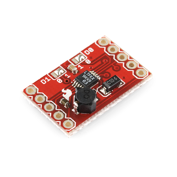
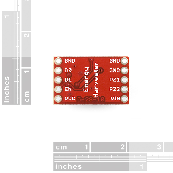
This breakout board uses the LTC3588 Piezoelectric Energy Harvester from Linear Technologies. This board can be used not only for harvesting piezoelectric energy, but solar energy as well. There is a bridge rectified input for piezo elements (PZ1 and PZ2) and a direct input (VIN) for DC sources. Both are clamped to 20V. In addition, the board can simply be used as a standalone nanopower buck regulator.
An ultralow quiescent current undervoltage lockout (UVLO) mode with a wide hysteresis window allows charge to accumulate on an input capacitor until the buck converter can efficiently transfer a portion of the stored charge to the output. In regulation, the LTC3588 enters a sleep state in which both input and output quiescent currents are minimal. The buck converter turns on and off as needed to maintain regulation.
Four output voltages (1.8V, 2.5V, 3.3V and 3.6V) are pin selectable with up to 100mA of continuous output current and comes pre-configured for an output of 3.3V. However, the output capacitor may be sized to service a higher output current burst. An input protective shunt set at 20V enables greater energy storage for a given amount of input capacitance.
- 950nA Input Quiescent Current (Output in Regulation – No Load)
- 450nA Input Quiescent Current in UVLO\
- 2.7V to 20V Input Operating Range
- Integrated Low-Loss Full-Wave Bridge Rectifier Up to 100mA of Output Current
- Selectable Output Voltages of 1.8V, 2.5V, 3.3V, 3.6V
- High Efficiency Integrated Hysteretic Buck DC/DC
- Input Protective Shunt – Up to 25mA Pull-Down at VIN ≥ 20V
- Wide Input Undervoltage Lockout (UVLO) Range
SparkFun Energy Harvester Breakout - LTC3588 Product Help and Resources
Changing Voltage Output
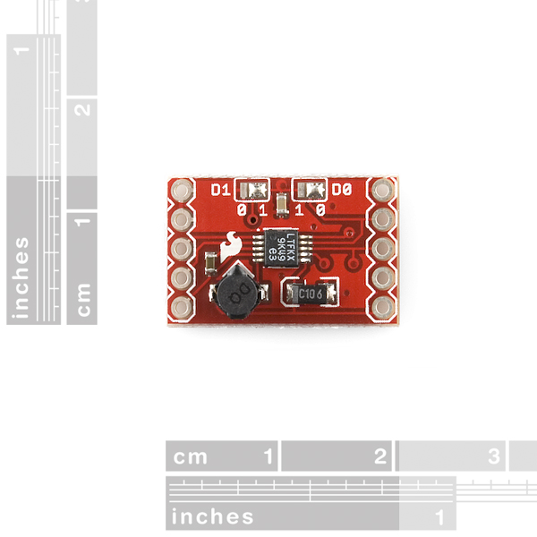
To change the output of the energy harvester you would need to move the solder jumper for either D1 or D0. Default is set to Vout = 3.3V:
(D1, D0) – VOUT
(0, 0) – 1.8V
(0, 1) – 2.5V
(1, 0) – 3.3V
(1, 1) – 3.6V
For more information, look at page 9 of the datasheet LTC3588 http://cds.linear.com/docs/en/datasheet/35881fb.pdf.
Piezo Vibration Sensing
Testing it with the smaller piezo element [ https://www.sparkfun.com/products/10293 ] in our storefront, it does work but you have to bang it on the edge of the table with a pen so there is enough vibration to generate power for the harvester. It's not efficient but it will work... eventually. You can see some small sparks on the piezo in the dark. It will probably be damaged by the time you generate enough energy.
Looking at the piezo using a oscilloscope, the MIDEV21BL had more vibrations and spikes than the piezo element. The piezos from MEAS loaded with masses had a significantly smaller spike than the other components.
Demo Video and Hookup
A MIDE V21BL energy harvesting piezo (retired) was used in the demo video => http://www.mide.com/products/volture/piezoelectric-vibration-energy-harvesters.php. The parts used include:
Try looking at this schematic to hook it up => https://drive.google.com/open?id=0B0jwgLkjMWzDdnFCWW4yc3RGM0E&authuser=0.
Here's an image of the application circuit wired up from the demo video => https://drive.google.com/open?id=0B0jwgLkjMWzDeFNuendDb0JCMWs&authuser=0.
Quick Test
For a quick test to see if it is working. The engineer that designed the breakout board suggested that you should try putting 5V through the Vin pin and see if you get 3.6V at the VCC side. If you are getting 3.6V at the Vcc pin, it verifies that the board is working.
I tried 3.3V and 5V but the energy harvester was not able to output any voltage at VIN. I then tried using 8V from my power supply set to 30mA and I was able to see an output of 3.3V based on the settings that my board was set to.
Core Skill: Soldering
This skill defines how difficult the soldering is on a particular product. It might be a couple simple solder joints, or require special reflow tools.
Skill Level: Noob - Some basic soldering is required, but it is limited to a just a few pins, basic through-hole soldering, and couple (if any) polarized components. A basic soldering iron is all you should need.
See all skill levels
Core Skill: Electrical Prototyping
If it requires power, you need to know how much, what all the pins do, and how to hook it up. You may need to reference datasheets, schematics, and know the ins and outs of electronics.
Skill Level: Competent - You will be required to reference a datasheet or schematic to know how to use a component. Your knowledge of a datasheet will only require basic features like power requirements, pinouts, or communications type. Also, you may need a power supply that?s greater than 12V or more than 1A worth of current.
See all skill levels
Comments
Looking for answers to technical questions?
We welcome your comments and suggestions below. However, if you are looking for solutions to technical questions please see our Technical Assistance page.
Customer Reviews
1 out of 5
Based on 1 ratings:
11 of 12 found this helpful:
Doesn't seem to last
I've burnt through two of these boards with the exact circuit shown in the video. My theory (tested with an Oscope) is sometimes the piezo spikes above 20 V and burns out an internal component. You'd think there'd be protection built in...
On the flip side, I've found that hooking up the piezo to a voltage rectifier using a few diodes, and then a capacitor provides a good, low cost solution.
Wondering: would this also work with a low-voltage TEG and a battery charger? http://www.tegmart.com/thermoelectric-generator-modules/tegpro-thermoelectric-generator-module-1-watt-2-vdc-low-temp/
What is so expensive about these boards? The chip it's based on only costs about $3:
https://octopart.com/search?q=LTC3588-1&start=0
Hello, I am working on a research project that involves the use of a microbial fuel cell and I was curious if this energy harvester and the LiPower boost converter, when used together, are capable of capturing the energy it produces. Thanks!
Good day I have already bought LTC 3588 for my research in piezoelectric energy harvesting my initial test is i only get .25MA which is low.. could somebody help the connectivity and circuitry that i may get perhaps greater than .25MA thanks for your help...
Hello, i bought this module but i am having problems trying to make it work. I am charging the input capacitance with the configuration shown in the first page of the PDF http://cds.linear.com/docs/en/datasheet/35881fc.pdf. As expected, when i charge the input above around 4.5 V i get a 3.3 V output but the input capacitance discharge itself really really quickly when i measure it, it seems like there is any kind of leakage, i would greatly aprecciate if you can help me, maybe it is a common problem.
How may days can we receive it if we order this? Bulacan,Philippines is our area. Thanks
That depends on your actual address, and shipping method (and sometimes what you order). The best way to tell is to add the items to your cart and hit checkout. The first checkout page will give you a list of shipping options and prices. Keep in mind that this does not include any time your government may hold the package in customs.
Prehaps an energy harvesting/storing tutorial is in order? I could be wrong, but short of the battery primer they prepared it does not seem like there is much instruction on how to go about utilizing such technology as lovely breakout board above, or any of the energy generating products on SFE. I personally am interested in using flexible solar panels in conjunction with piezoelectric sensors and energy harvesting and storing, but would greatly appreciate any light to be shed on such matters. Heck, even a tutorial on bike energy generation would be pretty helpful! /end friendly rant
Any direction to appropriate threads, tutorials, blogs, or forums would be greatly appreciated, and if they do not yet exist, HELP ;)
Thats what I am talking about. Well put Like H. The best I can do is tell you to search "piezo energy technologies"
Is anyone else thinking about making a self-sustained LED throwie?
How 'bout LED jewelry powered by the motion of the wearer?
I like it. Page four of this PDF has a few possible ways to harvest energy from the human body, including blood flow, body heat, and body motion. Perhaps the latter two could be combined to power jewelry or charge a cell phone.
Like my watch that "recharges itself" from the motion of my arm?
Yes, why isn't this more widely used? Especially in cellphones!?
Energy harvesting is great for things that use extremely small amounts of power, such as your wristwatch. Cellphones use a LOT of power; anything you could extract from heat and motion would just be a drop in the bucket.
What do you mean by "self-sustained"?
Probably solar powered, but I imagine one could harvest wind energy.
OK, I think it's because the posts above were mentioning body heat, arm motion and so on, but when I saw "harvest wind energy" I immediately flashed on a "nasal passage turbine", which sounds disgusting, but could it be done?
I have heard of folks using breathing to harvest energy, but I believe they usually go more for the stretching of the rib cage with each breath, rather than actual nasal air flow. If you figure out how to do it though, send us pictures! That would be awesome to see.
Sparkfun, Can you post on the LTC3588 product webpage the schematic used in the "Sparkfun Simple Sketches - Energy Harvest Breakout" video posted on the LTC3588 web page. thanks!
A MIDE V21BL energy harvesting piezo was used in the demo video => http://www.mide.com/products/volture/piezoelectric-vibration-energy-harvesters.php. It was wired on a mini breadboard with a basic red led, 330Ohm resistor, 10uF/25V electrolytic capacitor. Try looking at this schematic to hook it up => https://drive.google.com/open?id=0B0jwgLkjMWzDdnFCWW4yc3RGM0E&authuser=0.
Here's an image of the application circuit wired up from the demo video => https://drive.google.com/open?id=0B0jwgLkjMWzDeFNuendDb0JCMWs&authuser=0.
hi, i have set up my breadboard in the same way but the LED will not light up. Will this only work with a certain piezo? Is there a way to test the LTC3588 to make sure it is working properly?
Yes, the LTC3588 will only work with a certain piezo. You would need an energy harvesting piezo. It is listed on page 11 in Table 2 of the datasheet => http://cds.linear.com/docs/en/datasheet/35881fc.pdf . I have tested it with the piezos from our site and they do not produce a lot power. I have been unsuccessful with our piezo sensors to harvest any energy.
The development/breakout boards that are produced by SparkFun are usually tested on a pogobed and inspected by a technician for quality control before they are packaged and sent out. For a quick test to see if it is working. our previous engineer that designed the board suggested that you should try putting 5V through the Vin pin and see if you get 3.6V at the VCC side. If you are getting 3.6V at the Vcc pin, it verifies that the board is working.
Hmmm I am using a Piezoelectric Fiber Composite from ACI, which is listed on Table 2. My oscilloscope shows a peak voltage of about 40V, maybe that is too much for the breakout board?
OK so here is what I am doing to test the LTC3588: Arduino Uno 5V -> LTC3588 Vin, Arduino Uno GND -> LTC3588 GND, Oscilloscope + Probe -> Vcc, Oscilloscope - Probe ->GND (different GND on the same side as Vcc)
When I measure Vcc I am not reading any voltage. However, when i move the + Probe to D1 I am reading about 5V...what do you think?
Have you all looked at making a similar board for the LTC3588-2? Having outputs >3.6v would be helpful in LiPo charging.
Would it be possible to use this to charge a LiPo battery with solar cells grabbing energy from light flashes? Of course, pairing this with a LiPo charging circuit. If so, is it better to have a high Vin (20V), low (2.7V) or something in the middle?
You would need to look at the Joules of energy you're getting- specifically how long the light flashes last, and how much voltage and current you get from each one. Current * Voltage = Watts, Watts * Time = Joules. Find out how many watts of energy you need on the output, and for how long, that gives you the amount of joules you need and then calculate backward from that.
If the flashes are very quick and have a low duty cycle then you probably won't be able to power anything from them. But if they're frequent enough you could have those flashes cause the solar panel to put charge on a capacitor and then work from there. This part would be good at that since it sleeps until enough charge is on the input cap to efficiently convert it.
Hello what about connecting a piezo like this one: https://www.sparkfun.com/products/9196 I read that the harvester only works in the +2,7 +20V range, but the piezo works in the -90 +90, (more realistically -25V +25V), what component is needed to rectify the negative voltages?
This chip has internal rectification between PZ1 and PZ2. Check the datasheet, page 7 block diagram.
I bought a couple of these looking to have access to the LTC3588 in a breakout fashion. I have found - so far - that the access to the LTC3588 is somewhat limited. Let me start by saying that this board DOES work - but only at 3.3V and for limited configurations.
Not sure yet what exactly is possible with regard to accessing the LTC3588 pins and features. I took a look at the Eagle files to see where the LTC3588 pins were actually routed on this board.
The board seems to "hard wire" d0 and d1 to 3.3V using soldered pads - and even though d0 and d1 are accessible, my attempts to use them to select other voltages have not been successful. I have not yet tried removing the solder from the pads - but that might work from the schematic. The board obscures the LTC3588 Vin2 and SW from direct usage and access. The LTC3588 PGOOD pin is re-labeled EN. LTC3588 Vout is combined with LTC3588 SW and an inductor/capacitor to create the board's Vcc.
Again, this board DOES generate a current at 3.3V when something like a solar panel is correctly connected (using PZ1 and a resistor I found), but it may be limited in terms of other LTC3588 flexible usage.
Vin2 and SW don't look like a user would need access to them anyway. (I say this having not yet used the chip.)
However renaming Vout to Vcc and PGOOD to EN is annoying, but I'm guessing sparkfun did it to try and provide consistency with other boards for newbies wondering what-to-hook-up-to-what.
OK. An update just in case this might help somebody else. I was eventually able to switch the d0 and d1 "pins" from 3.3V (the default setting of d1=1 and d0=0). I went to 2.5V by setting d0=1 and d1=0 - basically reversing the default settings of the board. And.... it does work - it generates current at 2.5V. :-) But..... to do it I had to work hard to remove the solder bridges on the d0 and d1 pads - and then re-create solder bridges the opposite directions (look at the board and you'll see what I mean). This process was pretty "iffy" for me. It almost did not work and the board was getting pretty nasty looking near the pads by the time I was done. I wish there was an easier way to switch the state of d0 and d1 to change the output voltage - maybe a jumper???? That's my story anyway. Hope it helps somebody.
hello,, i want to implement solar panel application which is given in lTC3588-datasheet on this board.and i have some query regarding this my application. please help me to solve me this query. 1] if i want to apply same application for small size of solar panel such as [Voc=6.5V, p=0.5W and 70*55mm size] then can i apply? 2] what kind of changes i have to do in circuit in place of attached datasheet application zener Diod [IR05H4OCSPTR] , super capacitor[3F, 2.7V] , capacitor [100μF, 25V] , 9V battery and resistance[100ohms]? 3] can i use li-ion battery[mobiles battery]? 4] what is the purpose of battery in this circuit? means excess energy is stored in battery and when not available that we can use in our application? 5] Another query related this board is if i want to select Vcc as 1.8V then can i connect D0 and D1 pin directly to Gnd pin of board ? because GND pin and gnd's Do & D1 pads are shorted in the board. 6] How can get high for d0 and d1 ? means i have to solder it with high pads ? because too short distance between low and high in the board. please tell me if another way.
I was hoping to do the same thing you were trying to do. Not sure yet that it is possible in that the board seems to "hard wire" d0 and d1 and obscures Vin2 and SW from usage. I posted a full comment with all of my impressions.
I'm thinking about using this to convert breath energy in a Native American Flute to power a condensor mic.
When is this bad boy coming back in stock?
Im a bit confused regarding the pins and their connection, when i refer to the datasheet, there is a vin1 and vin2 and what do you do with the Vcc pin.
The board seems to "hard wire" d0 and d1 and obscures Vin2 and SW from usage. Vcc looks to be a combined SW and Vout. I posted a full comment with all of my impressions.
Can I used this to power your Bigtime watch ( https://www.sparkfun.com/products/11734 )? Should I have a battery in parallel with the rechargeable coin cell battery? 2.5V or 3.3V as the watch requires 3V? If I have it in parallel with the battery and the battery is fully charged and the sun is shining would the A increase so much that it would fry it? Any help would be appreciated. Thanks
Does the storage capacitor needs to store at least a 2.7V before it can operate the in-built regulator ?
The operating Voltage is 2.7V and above ? So does it means that the Storage capacitor needs to store at least 2.7V before the in-built regulators to work ?
I need a 3.6V output. Do I connect using the d0,d1 pins (between the gnd & en pins) OR should I use the d0,d1 pins on the top of board?
Hello, I built a datalooger with a Stalker microcontroller (Seeduino) using a multiplexer (Muxshield 1) to read temperature sensor. When powered by usb cable, the reading of sensor and unused port of the mux is very stable. However, when I use a battery pack (7.2V) and the energy harvester above set at 3.6V, the signal becomes unstable... from port to port of the MUX1, there is a succession of high and low bit-voltages, which create significant output uncertainties. When I remove the energy harvester and use a 3.6V battery, the signal still stable. So my conclusion is that the energy harvester is responsible for this "electrical" noise. I need a battery of higher voltage because we want to deploy the datalogger in remote and very cold region (need to keep a voltage of 2.2 V min at -40 degree C.
Is anyone have an idea on how removing this noise?
Thank you for your help/advices.
PS: I also tried the harvester using capacitors between the harvester and the microcontroller, but the problem still there.
researching "linear"'s dot com's "LTC3588"'s applications i wonder, which input devices one may use to generate the energy; (any device that generates at least >= 1.5V aa(a) battery charge's). besides some electronic components' vendors extremely expensive piezo elements ... is there any source you would recommend?
There are many sources you can use with this IC. The input is rectified which means you can use an AC signal (like a piezo), or you can bypass the rectifier and use any DC source, like a solar cell.
Can it be used as a high efficient voltage regulator from 3.3v -> 1.8v (since it's essentially a DC-DC buck converter)?
Hey does anybody know how to select the output voltage in this board? Thanks
Look at Table 1 on the top of page 9 of the datasheet. The photo of the board shows that D1 and D0 are both labelled well and set for 3.3V output.
Take a look at the CymbNet EnerChip CBC5300 as well, have used them in a couple of solar designs: http://goo.gl/PChfC
Nice discrete solution, includes caps and 100uAH thin-film batteries on board a DIP24 package. Package supports piezo, solar, thermo, AND RF in single package.
This breakout is a toy in comparison, and is only a single part of a complete energy harvesting solution.
can i connect the output directly to a battery to charge it? or will the current from the battery flow through the breakout board and destroy the IC?
is this breakout board set to 3.3 vout? i cant seem to select the voltage output to 1.8v. i tried connecting the d1 and d0 pin to gnd.
Yes. If you look at the top of the board, there are a set of pads labeled D1 on the left and D0 on the right. The D1 pad has a solder bridge to a high rail and the D0 pad has a solder bridge to a ground rail.
I am still a little confused about the advantage of the IC on the board. From my understanding I can use this breakout with A couple super caps. And I Can hook up some of the mini Solar cells to this IC and it will balance out there input power? Then I will get a steady voltage/current output? Even with the solar cells output bouncing current and voltage?
Where do you get the piezo device ? The PFC-W14 used in the example circuit doesn't look like its easily available. Has anyone used this with another piezo device ?
Thanks,
Zainul.
I've been playing with this chip and Mide Volture energy harvesters ( http://www.mide.com/products/volture/volture_catalog.php#raw ) for my Mosquino project. Most of these parts are now on Digi-key as well. (Disclaimer: I work at Mide for my day-job, so of course I am a little biased ;-)<br />
<br />
The "brass disk" style piezo transducers you find in e.g. singing greeting cards use the same active material (PZT) and can also be used to generate electricity. The performance is not the same, but they are much cheaper!<br />
<br />
PVDF sensors (sold as 'Piezo Vibration Sensor' on Sparkfun) will produce something too, just not on the same level as good ole PZT. This is a much less stiff material though, so it may be a good choice to harvest energy from something with a large range of motion or tight bending radius, e.g. the sole of a sneaker.<br />
<br />
Designed-for-purpose piezo energy harvesters are typically a cantilevered beam, similar to a diving board (clamped at one end and allowed to vibrate freely at the other). To get the most out of it, mass is added to the free end to tune the beam's natural frequency to match the vibration source. If you use the brass discs for vibration, use an enclosure/ring that holds it by its outside edge and add the mass at the center.<br />
Mosquino? sounds like your running a arduino project of a tiny power source. care to share your project??
That is exactly what it is :-) You can download it from http://code.google.com/p/mosquino/ . Beware, this is still a work in progress! Right now there is a mainboard, a selection of power shields for various power sources (Peltier, piezo, solar) and a few I/O shields, but not all of the I/O / peripherals have software support written yet. (It's not at all obvious on the source page, but use the 'Repository:' dropdown on the source page to switch between the code and PCB repositories.)
Hi Drmn4ea I have found your Blog and post very helpful on this subject and wanted to know if you could confirm my idea , I myself want to create the same power source for low consumption ICs but with one difference , ...Space or should i say the lak off... I want to use the this solar Cell http://www.sparkfun.com/products/9962 and this Piezo http://www.sparkfun.com/products/10293 both connected to the input of this energy harvester with a Super cap in parallel and output connected to the max 1555 battery charger chip. charging a coin cell 47Mah 3v battery. all of this in a space no bigger then the energy harvester it self. of cource i will need to redesign PCB for it but though id ask if you have similar product planned ? I want to think of it as a opportunistic battery charger rather then power supply .
all thoughts are welcome . sorry for my English , not my mother language
Hi, I recently ordered the chip and wanted to know how can i select the different prefixed voltages. I am just a bit confused about how i can set D1 and D0 values as there are no jumpers.
Waiting for your reply.
Set D1 and D0 high or low directly.
(D1, D0) - VOUT
(0, 0) - 1.8V
(0, 1) - 2.5V
(1, 0) - 3.3V
(1, 1) - 3.6V
This datasheet has a bunch of circuit diagrams.
Guys, here's a tip for designing energy harvesters which use rather small current sources, say 10uA.
Super Caps, such as the one linked below, are great for storing large amounts of power. But when it comes to storying power from a low-current source, you need to use a cap with a very low leakage current. Otherwise the cap will never charge or it will drain before you ever get to use the charge. Leakage current is basically a time-based inefficiency. The charge will simply disappear at a rate, which is 'usually' defined in a capacitor's data sheet.
Super caps, generally, have a high leakage current. If you are referencing certain published articles which mention super caps for harvesting, look again and see if they ever cover the leakage current issue for super caps...
How do you approach this issue? Well, you simply find a capacitor with a leakage current which is smaller than your harvester element's source current. Hopefully a good deal smaller.
Take a look at this one at Digikey
100uF 5uA Leakage NOSC107M002R0150
CAP OXI LOESR 100UF 2.5V 20% SMD
If you find any better parts, please post and let us know.
Much luck,
;)
R
Yea, the related super cap might not work for most low power applications.
We suggest using a low ESR, low leakage super cap, like this one (coming soon!):
http://www.mouser.com/ProductDetail/PowerStor-Cooper/M0810-2R5105-R/?qs=yoyprvkDL1kwUNCRKXlMzQ%3d%3d
Aerogel caps are also good for energy harvesting.
Hi,
I'm a little confused as to why all the caps being listed here are rated at 2.5V. Isn't the input cap supposed to be rated at the highest V_UVLO ? i.e. > 5V for a 3.3V output.
The 3588 datasheet has a 25V capacitor for storage.
Thanks,
Zainul.
If you are referring to the related item, you are correct, you do not want to connect only one of these to the input. You will need to connect at least another in series. Two 10F/2.5V caps in series equals one 5F/5V cap.
This is definatly one of the more interesting Sparkfun products as far as what you can do goes, although it really isn't cheap as far as the use it would generally be meant for (Small sensors). You'de kind of need something similiar but at a $15 or so price range for that if you want to make a bunch of them. Obviously this isn't that, but it looks promising. Despite my rambling, I might just buy one to mess with.
If you are making more than a few pieces, you would want to look into designing your own PCB. The IC can be purchased from Digikey or Linear for about $5.
wha?
can anyone explain what this does exactly?
can this thing be used to "wake up" a sleeping arduino with a knock?
if not, any suggestions on how that can be done?
thanks
It's designed to take very-low-power power sources at inconvenient voltages, and use them to power more normal microcontroller-type circuitry, intermittently if necessary (e.g. if there's only enough power to run the microcontroller for a few minutes every hour, it'll take care of the business of accumulating charge and then turning the load on and off).
Linear's appnote http://cds.linear.com/docs/Design%20Note/DN483.pdf has an overview of how they envision this chip being used.
Inconvenient voltages that are at least ~1.5v HIGHER than your desired output voltage. I've been poring over the data sheet trying to integrate this into a project for a month, and the piezo basically has to output more than 5v to be usable for a 3.3v power output.
What I can't really figure out is the maximum voltage the chip can take from the piezo - the data sheet seems to imply there's a clamping diode for ~18v, but then goes to say the maximum voltage allowed on that PZ input is 20v! Is this correct?
If that's the case, then this is only useful where your piezo output can reach more than 5v, but doesn't exceed 20v.
This chip has a protective shunt which will sink up to 25mA when the input voltage goes over 20V. Yes the maximum input is 20V, but it's pretty much impossible to exceed that unless you hook it up to a low-impedance source like a 120V electrical socket. A piezo element that gives you 100V open circuit should work just fine, and will give more energy than one that maxes out at 15V. When the chip starts sinking current, the voltage across the piezo terminals will be reduced.
I discovered this same thing. It would only start harvesting if I had at least 5v DC or 10v peak to peak AC in its stock jumper configuration. My piezo would have to really vibrate to get that high at the given input impedance.
Then you just need a different piezo. Piezo elements are layered to yield higher voltages; it's not uncommon to get thousands of volts from a piezo (where that's desirable). Match the piezo to your vibration mode and desired voltage range.